
Common Electronic Component Schematic Symbols
When creating new electronics, designers and engineers need a common language to describe the building blocks of their project. This language is composed of electronic component schematic symbols that define a component’s position, type, and function within a circuit and ultimately guide accurate PCB layout.
While experienced designers might recognize hundreds of symbols from memory, the sheer variety of components in modern electronics can be daunting. Furthermore, symbols can vary based on regional standards (ANSI vs. IEC), adding another layer of complexity. This guide explores the standards governing these symbols and provides a reference for the most common ones you will encounter in your schematic design.
What is an Electronic Component Schematic Symbol?
An electronic component schematic symbol is a standardized graphic used in circuit diagrams to represent a specific electrical component. Unlike a PCB footprint, which represents physical dimensions, the schematic symbol represents the component’s logical function and connectivity.
The Standards Behind the Symbols
To ensure consistency across the global electronics industry, symbols are governed by specific standards bodies:
- IEEE/ANSI 315-1975: The standard for Graphic Symbols for Electrical and Electronics Diagrams. Although technically deprecated, these symbols remain the dominant standard in the United States and are widely used in most ECAD software.
- IEC 60617: The international standard for graphical symbols. These are commonly used in Europe and often differ visually from their ANSI counterparts (e.g., a resistor is a rectangle in IEC, but a zigzag line in ANSI).
- IPC-2612-1: A newer standard that defines methodologies for generating schematic symbols, ensuring that complex, high-pin-count devices are represented clearly.
Key Differences Between IEEE/ANSI, IEC, and IPC Symbol Standards
While all three standards aim to ensure clarity and consistency in electronic schematics, they differ in scope and usage. IEEE/ANSI 315 focuses on traditional, widely adopted symbol shapes common in the United States; IEC 60617 emphasizes international uniformity with visually distinct symbol conventions used primarily in Europe; and IPC-2612-1 addresses modern design complexity by defining rules for creating scalable, unambiguous symbols for high-density and advanced components rather than prescribing fixed symbol shapes.
Historically, librarians had to build these symbols manually from datasheets. Today, engineers can save significant time by downloading verified symbols from trusted repositories like Ultra Librarian.
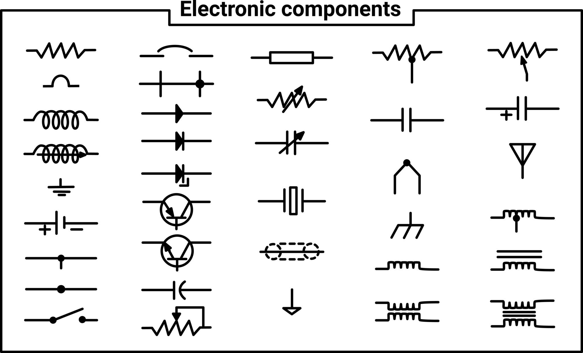
Common Electronic Component Schematic Symbols
Below is a reference table of the most common active and passive component symbols used in PCB design. Where two variants exist, the IEEE/ANSI style is typically prioritized in major ECAD tools.
Electronic Component Schematic Symbols
| Name | Symbol | Details |
| Resistor | A passive component that restricts the flow of current. | |
| Resistor (Light Dependent) / LDR | 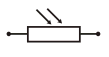 | A resistor whose resistance decreases as light intensity increases. |
| Resistor (Thermal) / Thermistor | 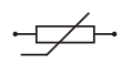 | A resistor whose resistance changes significantly with temperature. |
| Resistor (Variable) | A standard resistor with an adjustable resistance value. | |
| Potentiometer / Voltage Divider | 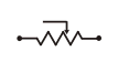 | Three-terminal variable resistors used for controlling voltage division. |
| Capacitor (Non-Polarized) | Standard capacitor for energy storage. Connections are interchangeable. | |
| Capacitor (Polarized / Electrolytic) | A capacitor that must be connected with specific polarities. | |
| Capacitor (Variable) | A capacitor where the capacitance value can be adjusted (user or factory preset). | |
| Inductor | A coil that stores energy in a magnetic field; it filters high-frequency noise. | |
| Diode (Junction) | A semiconductor that allows current to flow in only one direction. | |
| Diode (Light Emitting) / LED |  | A polarized diode that emits light when current flows through it. |
| Diode (Photo) |  | A diode that generates current when light strikes it (used in sensors). |
| Diode (Zener) | A diode that allows reverse current flow at a specific breakdown voltage; used for regulation. | |
| Diode Bridge |  | A module containing four to six diodes used to rectify AC to DC. |
| Transistor (NPN) |  | A Bipolar Junction Transistor (BJT) that switches ON when a high signal is present at the base. |
| Transistor (NJFET) |  | An N-Type Junction Field Effect Transistor, a voltage-controlled switch. |
| Transistor (PNP) | | A BJT that switches ON when a low signal is present at the base. |
| Transistor (PJFET) | | P-Type Junction Field Effect Transistor. |
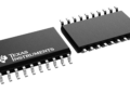
| Integrated Circuit / IC | 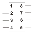 | Complex circuit (chip) containing miniaturized transistors and components. |
| Amplifier (Operational) / Op-Amp | 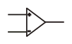 | An integrated circuit that amplifies the voltage difference between its two inputs. |
| Amplifier (Voltage) |  | Generic symbol for a circuit that increases the output signal voltage. |
| DC Power Supply | 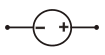 | Provides direct current (DC) to the circuit. |
| DC Power Supply (Variable) |  | Provides direct current with an adjustable output voltage. |
| Battery |  | A source of electrical energy, depicted as multiple cells in series. |
| AC Power Supply | 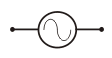 | Provides alternating current (AC) to the circuit. |
| Fuse | 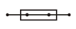 | A safety device that breaks the circuit if the current exceeds a safe limit. |
| Transformer (Iron-Cored) |  | A device that transfers energy between circuits to step the voltage up or down. |
| Transformer (2 Secondary Windings) |  | A transformer capable of producing multiple different output voltages. |
| Multiple Conductor Line |  | Represents a group of wires (bus) as a single line to simplify the schematic. |
| Branching Box |  | Represents a connection point or junction between multiple elements of a circuit node. |
| Motor | 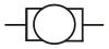 | Electromechanical engine controlled by circuit outputs. |
| Loudspeaker |  | An output device that converts electrical signals into sound. |
| Microphone |  | An input device that captures sound and converts it to electrical signals. |
| Filament Bulb | 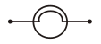 | A standard incandescent light bulb. |
| Voltmeter | 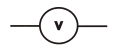 | A device used to measure electrical potential difference (voltage). |
| Ammeter | 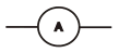 | A device used to measure electric current in amperes (AC or DC). |
| Galvanometer | 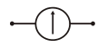 | A device used to detect and measure very small electric currents. |
| Cathode Ray Oscilloscope / CRO | 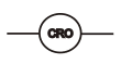 | A device used to visualize and compare input signals against time. |
| Electrical Appliance |  | A generic symbol for a device controlled by the PCB (e.g., TV, camera). |
| Socket Outlet (Telecom) |  | A connection point for telecom apps (phone, speaker, mic). |
| Socket Outlet (TV/Radio) |  | The connection point for antenna signals. |
The Importance of a Verified Library
While ECAD tools come with generic libraries containing basic resistors and capacitors, modern designs require specific, complex components, microcontrollers, connectors, and sensors that are not included by default. The best practice is to ensure schematic symbols do more than look correct by maintaining an intelligent link to the physical component used in PCB layout.
- Pin Mapping: The logical pins on the symbol (e.g., Pin 14 = VCC) must map perfectly to the physical pads on the footprint.
- Datasheet Compliance: The symbol must reflect the exact pinout specified by the manufacturer to avoid functional errors.
Instead of manually creating every symbol and risking a pin-swapping error, professional designers rely on comprehensive libraries.
Ultra Librarian helps by compiling all your sourcing and CAD information in one place and supports all popular ECAD applications with appropriate electronic component schematic symbols. By downloading verified schematic symbols, PCB footprints, and 3D models directly from our database, you ensure your design is built on a foundation of accuracy.
Working with Ultra Librarian sets your team up for success, ensuring streamlined, error-free design, production, and sourcing. Register today for free.


")