
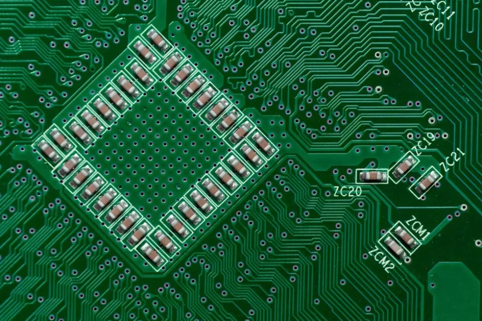
Ceramic capacitors on a circuit board
Multilayer Ceramic Capacitors (MLCCs) are used in a wide range of applications, from simple LED circuits to server power distribution networks. However, an MLCC may not behave at its nominal value after it is soldered onto a PCB. Ignoring this can result in voltage instability, audible noise, or unexpected failures in the field.
Proper MLCC capacitor selection requires understanding how the ceramic dielectric affects performance. Matching only the rated voltage and capacitance is insufficient; the limitations of the dielectric must be accounted for in the design.
The Anatomy of an MLCC
An MLCC consists of alternating layers of ceramic dielectric and metal electrodes (typically Nickel), stacked to increase the effective surface area. The capacitance is determined by the number of layers, the area of overlap, and the permittivity of the ceramic material.
Where n is the number of layers and d is the dielectric thickness. To shrink capacitors while maintaining high values, manufacturers must either increase the layer count or reduce the dielectric thickness. Miniaturization directly causes DC bias effects and voltage-dependent capacitance, which impact MLCC performance.
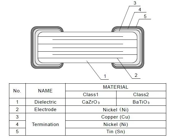
Example structure of a Class 1 and Class 2 MLCC
Dielectric Classifications
The most important decision in selecting an MLCC capacitor is choosing the dielectric class. The industry splits these into two primary categories based on temperature stability and material composition.
Comparison of Common Dielectrics
| Feature | Class 1 (C0G/NP0) | Class 2 (X7R) | Class 2 (X5R) |
| Dielectric Base | TiO2 (Paraelectric) | BaTiO3 (Ferroelectric) | BaTiO3 (Ferroelectric) |
| Temp Range | -55°C to +125°C | -55°C to +125°C | -55°C to +85°C |
| Temp Coeff | ±30 ppm/°C | ±15% | ±15% |
| DC Bias Effect | Negligible | Moderate to Severe | Severe |
| Aging | Negligible | ~2.5% per decade hour | ~5-7% per decade hour |
| Piezo Noise | None | Yes | Yes |
Class 1: C0G/NP0
Class 1 capacitors, represented with the code C0G or NP0, use a paraelectric material like Titanium Dioxide (TiO2) or Calcium Zirconate (CaZrO3) modified with rare earth oxides. Since they are paraelectric, they do not form magnetic dipoles that align with voltage fields.Class 1 capacitors, represented with the code C0G or NP0, use a paraelectric material like Titanium Dioxide (TiO2) or Calcium Zirconate (CaZrO3) modified with rare earth oxides. Since they are paraelectric, they do not form magnetic dipoles that align with voltage fields.Class 1 capacitors, represented with the code C0G or NP0, use a paraelectric material like Titanium Dioxide (TiO2) or Calcium Zirconate (CaZrO3) modified with rare earth oxides. Since they are paraelectric, they do not form magnetic dipoles that align with voltage fields.
- Stability: Rock solid. Capacitance changes negligibly with temperature, voltage, or time.
- Use Cases: Timing circuits, RF matching networks, and precision analog filters.
- Limitation: Low volumetric efficiency. You typically won’t find C0G caps larger than 100 nF to 470 nF without moving to massive, expensive package sizes.
Class 2: X7R, X5R
Class 2 capacitors use Barium Titanate (BaTiO3), a ferroelectric material with a massive dielectric constant (K). This allows for huge capacitance values in tiny packages (e.g., 22 µF in an 0603).Class 2 capacitors use Barium Titanate (BaTiO3), a ferroelectric material with a massive dielectric constant (K). This allows for huge capacitance values in tiny packages (e.g., 22 µF in an 0603).
- Trade-off: The high K comes with severe non-linearity. Capacitance shifts wildly with temperature and applied DC voltage.
- Use Cases: Power supply decoupling, bulk capacitance, bypass.
The DC Bias Trap
This is where 90% of selection errors happen. When you apply a DC voltage across a Class 2 capacitor, the electric dipoles in the Barium Titanate structure align with the field, locking them in place. Once “locked,” they cannot respond to AC ripple currents, effectively reducing the capacitance.
This loss is not trivial. A generic 10 µF 6.3V X5R capacitor in a 0402 package might act as a 1.5 µF capacitor when operating at 5V. That is an 85% loss of capacitance.
Rule of Thumb:
- The higher the capacitance density (more µF in a smaller package), the worse the DC bias effect.
- A 10 µF 0805 X7R will retain more capacitance at 5V than a 10 µF 0402 X5R.
- Voltage rating matters. A 10 µF 16V capacitor operating at 5V will perform better than a 10 µF 6.3V capacitor at 5V.
Aging: The Logarithmic Decay
Class 2 capacitors lose capacitance over time, even when sitting on a shelf. This is due to the crystal structure relaxing into a lower energy state. The rate is logarithmic, typically described as a percentage loss “per decade hour.”
- 1 to 10 hours: Small loss.
- 10 to 100 hours: Another step down.
- 100 to 1,000 hours: And so on.
X7R capacitors typically lose ~2.5% per decade hour, while X5R can lose up to 7%. The good news? The process resets (de-aging) whenever the capacitor is heated above its Curie point (approx 125°C). Soldering the part effectively resets the clock. However, for precision circuits that must hold tolerance for years without thermal cycling, Class 2 won’t do.
Practical Application Tips
1. Decoupling and Low ESL
For digital ICs, inductance is the enemy. The Equivalent Series Inductance (ESL) depends largely on the package size, not the value. A 0201 package has significantly lower ESL than a 1206.
- Strategy: Place small, low-ESL capacitors (0201 or 0402) closest to the IC pins to handle high-frequency transients. Place larger bulk capacitors (0805 or 1210) slightly further away to handle lower-frequency energy demands.
2. Piezoelectric Noise
Because Class 2 dielectrics are piezoelectric, they expand and contract with voltage changes. If your voltage rail has ripple in the audible range (20 Hz – 20 kHz), the capacitor acts as a speaker. The PCB acts as a sounding board, amplifying the noise.
- Fix: Use acoustically silent MLCCs (which use softer conductive epoxy termination), switch to tantalum/polymer caps (non-piezo), or change the layout to reduce board flex.
3. Voltage Derating for Reliability
While ceramic caps don’t fail catastrophically from mild over-voltage as tantalums do, they are prone to cracking. A common industry practice is to derate voltage by 50%.
- Example: For a 12V rail, use at least a 25V-rated MLCC. This helps mitigate DC bias loss and provides a buffer against voltage spikes that could crack the dielectric.
Tools of the Trade
Stop guessing. The “nominal” values in a datasheet are testing conditions (usually 0V DC bias, 1 kHz), not real-world conditions. Use vendor simulation tools to see the actual capacitance at your operating voltage and temperature.
- Murata SimSurfing: Excellent for visualizing DC bias curves and downloading SPICE models.
- KEMET K-SIM: Allows you to plot impedance vs. frequency and temperature rise.
- Würth REDEXPERT: Great for comparing real-world losses.
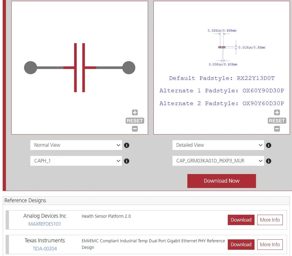
Symbol, footprint, and reference designs of a Murata Class 2 MLCC found on Ultra Librarian
Engineer’s Checklist to MLCC Capacitor Selection
Before finalizing your BOM, run your MLCC capacitor selection through this checklist:
- Check DC Bias: Have I looked up the capacitance vs. voltage curve? Do I have enough effective capacitance at the operating voltage?
- Package Size vs. Voltage: Am I trying to squeeze too much capacitance into too small a package, thereby ruining the effective value?
- Temperature: Is the circuit environment within the X5R limit (85°C)? If it’s an automotive or industrial design, have I switched to X7R or X8R?
- Audio Frequencies: Is there a significant ripple between 20 Hz and 20 kHz? If so, have I considered the piezoelectric noise risk?
- Cracking Risk: Are the large capacitors (1206 and up) placed near the edge of the board or near connectors where flexing might crack them? (Consider “soft termination” or “flex-term” variants).
- Derating: Have I applied a 50% voltage derating buffer?
MLCC capacitor selection is a balancing act of physics and geometry. By respecting the limitations of the dielectric and verifying performance with simulation tools, you ensure your 10 µF capacitor actually behaves like one when it matters most.
Ready to perfect your MLCC capacitor selection? Download verified symbols, footprints, and 3D models for popular ECAD applications from worldwide distributors instantly on Ultra Librarian.
Working with Ultra Librarian sets your team up for success, ensuring streamlined and error-free design, production, and sourcing. Register today for free.


 compared to a traditional USB-A cord (right).")

