
.
Microcontrollers like an Arduino or an STM32 are excellent for logic, but they lack the current-carrying capacity to drive heavy loads, such as motors, directly. The L298N is an industry-standard solution to this problem. Produced by STMicroelectronics, this dual H-bridge high-current motor driver is capable of controlling the speed and direction of two DC motors or one stepper motor. This guide breaks down the L298N datasheet to show the technical specifications, physical pinout, and practical application requirements for this versatile IC.
What is the L298N?
The L298N is a high-voltage, high-current dual full-bridge driver designed to accept standard TTL logic levels. It drives inductive loads, including relays, solenoids, DC motors, and both unipolar and bipolar stepper motors. More specifically, the L298N driver contains two H-bridge circuits, each allowing current to flow through a motor (or coil) in either direction, enabling bidirectional control.
L298N Datasheet Specifications
Exceeding the operating limits stated in the L298N Datasheet can lead to immediate failure of the silicon.
Absolute maximum ratings
| Parameter | Value | Unit |
| Power supply | 50 | V |
| Logic supply voltage | 7 | V |
| Input and enable voltage | –0.3 to 7 | V |
| Peak output current (each channel): • Non repetitive (t = 100 ms) • Repetitive (80% on –20% off; ton = 10 ms) • DC operation | 3 2.5 2 | A |
| Sensing voltage | –1 to 2.3 | V |
| Total power dissipation (tcase = 75 °C) | 25 | W |
| Junction operating temperature | –25 to 130 | °C |
| Storage and junction temperature | –40 to 150 | °C |
Technical Note: Voltage Drop
One critical detail often overlooked is the voltage drop across the output stage. Because the L298N uses bipolar transistors rather than MOSFETs, there is a cumulative drop of about 1.5V to 2.5V between the supply voltage (Vs) and the motor terminals. This must be accounted for in your power budget.
Pinout and Functional Descriptions
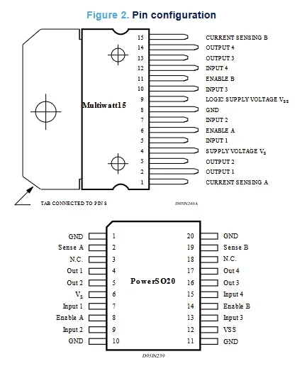
The L298N is manufactured in two primary packages: the Multiwatt15 (through-hole version) and the PowerSO20 (surface mount version). While pin numbering varies by package, the functional groups remain the same:
- Outputs (OUT1 through OUT4): These pins connect directly to the motor terminals. OUT1 and OUT2 serve Bridge A, while OUT3 and OUT4 serve Bridge B.
- Logic Inputs (IN1 through IN4): These accept TTL signals from the MCU to control the bridge state. For a DC motor, setting one input HIGH and the other LOW sets the direction.
- Enable Pins (ENA, ENB): These act as the “on/off” switch for each bridge. In most designs, a Pulse Width Modulation (PWM) signal is applied to these pins to control the motor speed.
- Current Sensing (SENS A, SENS B): These pins are located at the bottom of each H-bridge. They allow an external sensing resistor to be connected to ground to monitor motor current. If current sensing is not needed, these pins must be tied directly to ground.
- Supply Pins (Vs, Vss): The Vs pin provides the high-voltage power for the motors, while Vss provides the 5V logic power for the internal circuitry.
- Ground (GND): This is the common ground reference for both the high-power motor supply and the low-power logic supply.
Package Comparison: Multiwatt15 vs. PowerSO20
| Feature | Multiwatt15 | PowerSO20 |
| Mounting Style | Through-Hole (Vertical) | Surface Mount (SMD) |
| Total Pins | 15 | 20 |
| Cooling Method | External Bolt-on Heatsink | PCB Copper Pour / Thermal Vias |
| Best Used For | High-power, high-heat apps | Compact, automated SMT assembly |
| GND Connection | Single Pin (Pin 8) | Multiple pins connected to a thermal slug |
While the PowerSO20 is better suited to compact designs, the Multiwatt15 remains the standard for high-power motor control due to its superior cooling. If your PCB layout uses the SMT version, ensure the thermal pad is correctly defined in your CAD library to prevent the chip from overheating during operation.
Motor Control Wiring Basics
To drive a DC motor, connect the motor to OUT1 and OUT2. The logic follows this pattern:
- Forward: IN1 = High, IN2 = Low
- Reverse: IN1 = Low, IN2 = High
- Brake: IN1 = High, IN2 = High (or Low/Low)
Stepper Motor Control
To drive a bipolar stepper motor, the two coils of the motor should connect to Bridge A (OUT1/OUT2) and Bridge B (OUT3/OUT4). The MCU must step through a specific logic sequence on IN1 through IN4 to rotate the motor.
Practical Implementation Notes
Heat Dissipation
At its maximum rated current of 2A per channel, the L298N generates significant heat. The datasheet indicates that a large heatsink is mandatory for high-current applications. Without thermal management, the chip’s internal protection will trigger, or the part will suffer permanent damage.
External Diodes
Unlike some modern drivers, the L298N does not have internal freewheeling diodes. When the motor stops, it generates an inductive spike (back-EMF). You must place 8 fast-recovery diodes (e.g., 1N5819 Schottky diodes) on your PCB to protect the driver from these spikes.
Frequently Asked Questions
Can the outputs of the L298N dual H-bridge motor driver be connected in parallel to drive a single motor?
Yes. The two H-bridges (Bridge A and Bridge B) can be connected in parallel to drive a single DC motor with higher current capacity. This is done by tying the corresponding outputs together (OUT1 with OUT3, and OUT2 with OUT4) and applying identical control signals to both bridges.
What is the minimum voltage for Vs?
The motor supply voltage must be at least 2.5V higher than the logic supply voltage (Vss) for the internal level shifters to work correctly.
Why is my motor spinning slowly?
Check the voltage drop mentioned in the L298N Datasheet. If you provide 12V at the input, the motor may only receive 9.5V.
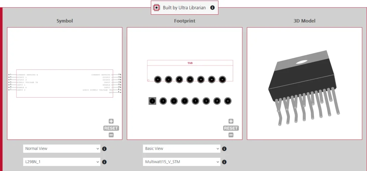
How Ultra Librarian Helps
Integrating a power driver into your PCB layout requires precision. The Multiwatt15 package has staggered pins that are difficult to draw manually. Ultra Librarian provides verified footprints, schematic symbols, and 3D models that match the L298N datasheet exactly, ensuring your physical board meets the datasheet specifications. If you’re looking for CAD models for common components or the L298N driver, Ultra Librarian helps by compiling all your sourcing and CAD information in one place.
Working with Ultra Librarian sets your team up for success, ensuring streamlined and error-free design, production, and sourcing. Register today for free.


")