Adding temperature sensing to a board usually comes down to two questions: How many sensors does the design need, and how many microcontroller general-purpose input/output (GPIO) pins can be dedicated to them?
The DS18B20 answers both. This digital thermometer from Analog Devices (formerly Maxim Integrated) reports temperature over a single data line, so one GPIO can serve the whole bus. A factory-programmed 64-bit read-only memory (ROM) code gives each sensor a unique address, so the host can identify and read many sensors on that same line. That combination makes it a common choice for HVAC monitoring, equipment temperature logging, and distributed process control where sensors must sit far from the controller.
This article walks through the DS18B20 datasheet, including the pinout, key specifications, the 1-Wire protocol, programmable resolution, power modes, common design mistakes, the DS18B20 vs DHT22 decision, and where to find verified CAD models.
Inside the DS18B20 Datasheet: Pinout and Package Options
The DS18B20 datasheet lists three package options with different pin assignments. Package selection depends on available board space and whether the design requires a through-hole or surface-mount component.
Pinout by Package
| Pin Function | TO-92 Pin | SO-8 Pin (DS18B20Z) | µSOP Pin (DS18B20U) |
| GND | 1 | 5 | 4 |
| DQ (data) | 2 | 4 | 1 |
| VDD | 3 | 3 | 8 |
| N.C. | None | 1, 2, 6, 7, 8 | 2, 3, 5, 6, 7 |
DQ carries both data and, in parasitic power mode, the sensor’s supply current, so keep the DQ trace away from noisy digital traces. VDD is optional; in parasitic mode it must be tied to ground rather than left floating.
DS18B20 Datasheet Key Electrical Specifications
- Operating temperature: -55 °C to +125 °C. Accuracy is ±0.5 °C from -10 °C to +85 °C and widens to ±2 °C at the extremes.
- Supply voltage: 3.0 V to 5.5 V for external power. Parasitic mode draws power from DQ.
- Standby current: typically 750 nA, up to about 1 mA during a temperature conversion.
- Resolution: programmable from 9 to 12 bits. The available settings provide steps from 0.5 °C down to 0.0625 °C.
How the DS18B20 1-Wire Protocol Works
The 1-Wire protocol needs only one data line plus ground between a host microcontroller and one or more DS18B20 sensors. This low pin requirement can simplify interfacing sensors with a microcontroller when GPIO availability is limited. The bus idles high through a single pull-up resistor, and every device uses an open-drain output so it can release the bus for other devices.
Multidrop capability comes from a factory-programmed 64-bit ROM code in each DS18B20:
- 8-bit family code: identifies the part as a DS18B20.
- 48-bit serial number: provides the device-specific portion of the ROM code so the host can distinguish sensors on the same bus.
- 8-bit cyclic redundancy check: lets the host verify the ROM code was read correctly.
The host microcontroller uses ROM commands to find and select sensors on the bus.
- Search ROM lets the host discover the unique ROM codes of all connected devices.
- Match ROM selects one specific sensor by its unique 64-bit ROM code, allowing subsequent commands to target only that device.
- Skip ROM bypasses individual addressing and sends the next command to every sensor on the bus. Use it only for commands every sensor can act on at once, such as starting a conversion. Reading results after Skip ROM with several sensors on the bus causes data collisions.
Programmable Resolution and Conversion Time
Every DS18B20 ships set to 12-bit resolution, and the host can trade resolution for speed by writing the configuration register’s R1 and R0 bits. Saving the setting to the sensor’s EEPROM (electrically erasable programmable read-only memory) keeps it through power cycles.
| R1 | R0 | Resolution | Max Conversion Time |
| 0 | 0 | 9-bit (0.5 °C step) | 93.75 ms |
| 0 | 1 | 10-bit (0.25 °C step) | 187.5 ms |
| 1 | 0 | 11-bit (0.125 °C step) | 375 ms |
| 1 | 1 | 12-bit (0.0625 °C step, default) | 750 ms |
Lower resolution settings finish up to eight times faster than 12-bit mode. For a design polling many sensors in a fast control loop, dropping to 9- or 10-bit resolution can matter more than the extra precision.
Reading the Temperature Data
After a conversion, the host reads the 16-bit temperature result from the scratchpad, the sensor’s nine-byte working memory. The result is a two’s complement value, and at 12-bit resolution each count equals 0.0625 °C. A reading of +85 °C right after power-up is the reset value, not a measurement.
Powering the DS18B20: Pull-Up Resistor and Power Modes
Every DS18B20 design needs a pull-up resistor on DQ, since the pin is open-drain and cannot drive the bus high by itself. The datasheet specifies roughly 5 kΩ for the 1-Wire bus generally, and its reference circuits use 4.7 kΩ between DQ and the supply rail.
The DS18B20 supports two power arrangements, set by how VDD is wired:
- External power mode: VDD connects to a 3.0 V to 5.5 V supply, with GND and DQ completing the connection. The bus stays free for other traffic during a conversion.
- Parasitic power mode: VDD connects to GND, and the DS18B20 draws power from DQ through an internal capacitor. During temperature conversion, current demand can exceed what the normal bus pull-up provides, so the reference circuit uses a strong pull-up to hold DQ high. The strong pull-up must engage right after the conversion command and hold through the conversion, so the bus is unavailable to other devices until it finishes. For high-temperature designs, use external power instead.
Common DS18B20 Design Mistakes
A few recurring design mistakes cause many DS18B20 problems.
- Missing pull-up resistor: without a pull-up on DQ, the bus cannot reach a valid high level and devices may fail to respond. The resulting communication failure can appear as a -127 °C reading or a timeout in common software libraries.
- Bus length pushed too far: a basic port pin with a simple resistor pull-up is reliable only to about 3 meters, per Analog Devices’ Application Note 148. Longer runs need a dedicated line driver and a lower-value pull-up, or the bus starts missing reset pulses.
- Assuming a fixed sensor count: each DS18B20 has a unique 64-bit ROM code, so true address collisions are rare. The real risk is a host that skips Search ROM enumeration and hardcodes a sensor count, which breaks the moment a sensor is added, removed, or fails.
DS18B20 vs DHT22: Choosing a Temperature Sensor
The DHT22 is a common alternative for projects that also need humidity, and the two sensors differ in more than what they measure.
| Parameter | DS18B20 | DHT22 |
| Measures | Temperature only | Temperature and humidity |
| Temperature range | -55 °C to +125 °C | -40 °C to +80 °C |
| Temperature accuracy | ±0.5 °C (-10 °C to +85 °C) | ±0.5 °C typical |
| Resolution | 0.5 °C to 0.0625 °C (9 to 12 bits) | 0.1 °C |
| Bus addressing | Unique 64-bit ROM code, multidrop | No individual addressing, one sensor per pin |
| Time per reading | 93.75 ms to 750 ms (max conversion time) | about 2 seconds |
For a design that needs many sensors on one bus, a wide temperature range, or configurable resolution, the DS18B20 is the better fit. For a single-point station that also needs relative humidity, the DHT22 saves a second sensor and a second data pin.
Sourcing Verified DS18B20 CAD Models
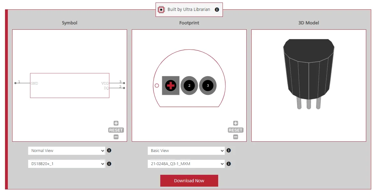
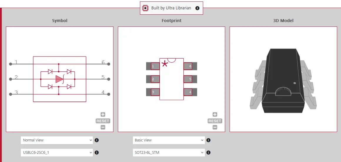
Working from the DS18B20 datasheet is only part of preparing the PCB layout. The TO-92, SO-8, and µSOP packages each require footprint geometry that matches the manufacturer’s dimensions. Incorrect pad spacing or pitch can cause clearance problems or poor solder joints. Ultra Librarian provides verified symbols, footprints, and 3D/STEP models for the DS18B20 and its DS18B20Z and DS18B20U manufacturer variants. The models are available for popular ECAD applications and are sourced from worldwide distributors.
Ready to turn the DS18B20 datasheet into a verified footprint? Register today for free and download models from Ultra Librarian, built for PCB designers who would rather skip the busy work.

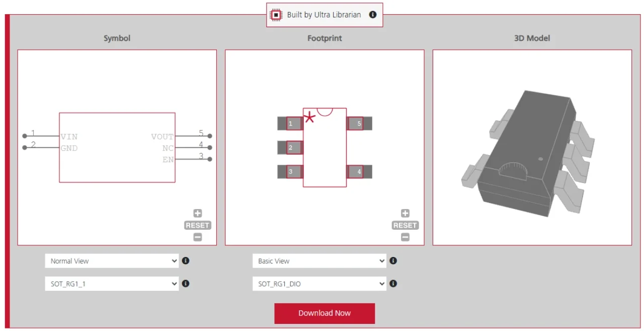
 If you’re looking for any of our component footprints or models, we have readily available and free options for you and your design team. Search our library for the solution you’ve been looking for.