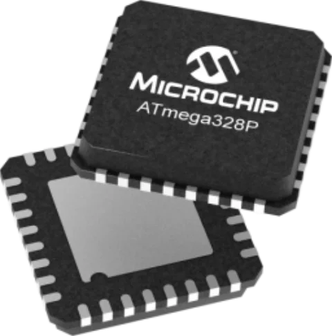
If you have ever built a project using an Arduino Uno, you have already worked with the ATmega328P Microcontroller. Originally developed by Atmel (now part of Microchip Technology), this 8-bit AVR RISC-based microcontroller is arguably one of the most famous ICs in the maker and embedded engineering communities.
In this guide, we will translate the technical specifications of the ATmega328P Microcontroller datasheet into practical, actionable context, helping you map your Arduino knowledge to real-world applications.
ATmega328P vs. ATmega328
While they are functionally identical in terms of architecture, memory, and pinout, the “P” stands for picoPower.
Microchip’s picoPower technology provides notable power efficiency for battery-operated devices. The ATmega328P features:
- Lower Power Consumption: The chip draws significantly less current in active and sleep modes.
- Brown-Out Detection (BOD) Disable: The “P” variant allows you to disable the BOD circuit during sleep via software, saving crucial microamps in low-power IoT applications.
- True 1.8V Operation: While both can operate at low voltages, the P variant maintains better stability and efficiency at the 1.8V boundary.
If your device is battery-powered, always specify the ATmega328P.
Key Specifications of ATmega328P Microcontroller
The datasheet is filled with hardware registers and architecture diagrams. Here is how those raw specs translate to the Arduino functions you already know.
Memory Configuration
- 32 KB Flash: This is where your code (sketch) lives. Note that the bootloader (which allows programming via USB) occupies a small portion of this (usually 0.5 KB to 2 KB).
- 2 KB SRAM: This holds your runtime variables. Running out of SRAM causes silent crashes in Arduino projects.
- 1 KB EEPROM: Non-volatile memory for saving settings (like calibration data) that persist even when power is removed, accessible via an EEPROM.h library.
Timers and PWM (analogWrite)
The ATmega328P has three hardware timers. In the Arduino environment, these handle background tasks:
- Timer0 (8-bit): Used for time-keeping functions like millis(), micros(), and delay(). It also controls PWM on pins D5 and D6.
- Timer1 (16-bit): Controls PWM on pins D9 and D10. Because it is 16-bit, it is often used by a Servo.h library for precise motor control.
- Timer2 (8-bit): Controls PWM on pins D3 and D11. Used by a Tone() function.
Takeaway: The analogWrite() function is simply a wrapper that configures hardware timers to output a duty cycle.
Analog-to-Digital Converter (analogRead)
The chip features a 10-bit successive approximation ADC.
- When you call analogRead(), the microcontroller samples the voltage on the specified pin and maps it to a digital value between 0 and 1023.
Pinout and Arduino Pin Mapping
Understanding how to connect the ATmega328p microcontroller pinout to the Arduino IDE pin labels “D0-D13” or “A0-A5” is critical when designing your schematic. The ATmega328P organizes its I/O into three main ports: Port B (PB), Port C (PC), and Port D (PD).
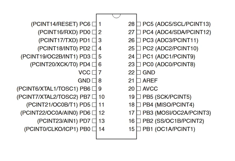
ATmega328P 28-pin Dual In-line and Arduino Pin Connection
| Arduino Pin | Port / physical Pin | Primary Function | Alternate / Hardware Function |
| D0 | PD0 (Pin 2) | Digital I/O | RXD (UART Receive) |
| D1 | PD1 (Pin 3) | Digital I/O | TXD (UART Transmit) |
| D2 / D3 | PD2 / PD3 (Pins 4, 5) | Digital I/O | External Interrupts (INT0, INT1) |
| D4 – D7 | PD4 – PD7 (Pins 6, 11-13) | Digital I/O | Timer inputs, PWM (D5, D6) |
| D8 – D10 | PB0 – PB2 (Pins 14-16) | Digital I/O | SPI (SS), PWM (D9, D10) |
| D11 | PB3 (Pin 17) | Digital I/O | MOSI (SPI) / PWM |
| D12 | PB4 (Pin 18) | Digital I/O | MISO (SPI) |
| D13 | PB5 (Pin 19) | Digital I/O | SCK (SPI) / Built-in LED |
| A0 – A5 | PC0 – PC5 (Pins 23-28) | Analog Input | Can also be used as Digital I/O (D14-D19). A4/A5 are also I2C (SDA/SCL). |
Important Note for Surface Mount Designs: If you upgrade to the TQFP-32 or MLF-32 (VQFN) packages, you gain two extra analog pins: ADC6 and ADC7. These are analog-only inputs and cannot be used as digital I/O.
Typical Application: Arduino Uno R3 Schematic Reference
To build a standalone, Arduino-compatible ATmega328P circuit, you must include the following subsystems:
1. Power and Decoupling
The ATmega328P requires a stable 5V (or 3.3V) supply.
- VCC and AVCC (Analog VCC) must be tied to your positive power rail.
- Decoupling: Place a 100nF (0.1µF) ceramic capacitor as physically close as possible to the VCC/GND and AVCC/GND pins to filter high-frequency noise and prevent erratic processor behavior.
2. The Clock Circuitry (16 MHz)
While the chip has an internal 8 MHz oscillator, the Uno runs at 16 MHz for precise timing, which is vital for stable UART serial communication.
- The Crystal: Connect an external 16 MHz quartz crystal across the XTAL1 and XTAL2 pins, accompanied by two 22pF load capacitors shunting both pins to ground. (Note: The official Uno R3 uses a ceramic resonator with built-in capacitors to save space.)
3. The Auto-Reset Circuitry
To allow the Arduino IDE to upload code over USB without pressing a physical button, you need a specific reset circuit.
- Pull-up: The RESET pin is active-low. Connect a 10kΩ pull-up resistor between the RESET pin and VCC to prevent accidental resets.
- Spike Protection: Place a 1N4148 diode in parallel with the 10kΩ resistor (cathode to VCC) to prevent high-voltage spikes from accidentally triggering High-Voltage Programming mode.
- The DTR Capacitor: Connect a 100nF capacitor between the RESET pin and the DTR (Data Terminal Ready) line of your USB-to-Serial converter. This turns a continuous logic-low signal into a brief pulse, rebooting the chip exactly when the IDE begins uploading.
4. Serial Protection (RX/TX)
If you are routing the ATmega328P’s RXD and TXD pins to an external USB bridge (like an FTDI chip or ATmega16U2):
- Place 1kΩ resistors in series on these communication lines. This prevents short circuits and protects the pins if you accidentally configure D0/D1 as outputs in your code while the USB chip is simultaneously trying to drive them.
Beyond Arduino: Bootloaders and Bare-Metal Programming
To use a raw, factory-fresh ATmega328P with the Arduino IDE, it must first have a bootloader burned onto it.
Bootloader For ATMega328P
The bootloader (like Optiboot) is a small piece of code placed in a specific section of the Flash memory. Upon reset, it listens to the UART (RX/TX) pins for incoming programming data. If it hears data, it writes that data to the rest of the Flash memory. This is what allows you to program an Arduino via a simple USB cable rather than requiring a dedicated hardware programmer (like an Atmel-ICE).
To burn a bootloader to a blank chip on a custom PCB, you must expose the ICSP (In-Circuit Serial Programming) header, which utilizes the SPI pins (MISO, MOSI, SCK, RESET, VCC, GND).
Bare-Metal Programming
For commercial products, engineers often bypass the Arduino IDE and write “bare-metal” C or C++ using AVR-GCC.
Why? Because Arduino functions like digitalWrite() carry a lot of software overhead to ensure they are user-friendly and safe. In bare-metal programming, you manipulate the port registers directly.
For example, turning on the LED on pin D13 (Port B, Pin 5):
- Arduino Code: digitalWrite(13, HIGH); (Takes several dozen clock cycles).
- Bare-Metal Code: PORTB |= (1 << PB5); (Executes in just 1 or 2 clock cycles).
Bare-metal programming results in much smaller compiled file sizes and vastly superior execution speeds, allowing you to extract maximum performance from the 8-bit architecture.
Sourcing CAD Models for the ATmega328P
Translating this MCU into your PCB design requires flawless physical dimensions. The ATmega328P is widely available in two main configurations for custom designs:
- DIP-28 (PDIP): Ideal for through-hole soldering, socketing, and breadboard prototyping.
- TQFP-32 / MLF-32: The surface-mount variants. These are essential for miniaturized, modern PCB layouts (and offer the bonus ADC6/ADC7 pins).
If you’re looking for CAD models for common components or the ATmega328P microcontroller, Ultra Librarian provides instant access to verified, IPC-compliant schematic symbols, PCB footprints, and 3D STEP models for the entire ATmega328P family for many popular ECAD applications.
Working with Ultra Librarian sets your team up for success, ensuring streamlined and error-free design, production, and sourcing. Register today for free.


")