Standard logic levels have shifted from 5V to 3.3V over the last decade, making voltage translation a constant requirement in modern electronics. The AMS1117 is one of the most popular low-dropout (LDO) linear regulators used to bridge this gap. You will find this IC on almost every Arduino-compatible board, ESP8266 module, and various power-management sub-circuits. This guide breaks down the technical details found in the AMS1117 datasheet to help you implement this regulator correctly in your next project.
What is the AMS1117 Linear Regulator?
The AMS1117 is a three-terminal linear regulator designed to provide a stable output voltage while handling up to 1A of load current. It belongs to the Low-Dropout Regulator (LDO) family, meaning it can maintain regulation even when the input voltage is very close to the output voltage.
The AMS1117 is available in two primary configurations:
- Fixed Versions: Pre-set at the factory for specific voltages: 1.2V, 1.5V, 1.8V, 2.5V, 2.85V, 3.3V, and 5.0V.
- Adjustable Version: Allows the user to set the output voltage using an external resistor divider. The adjustable version maintains a 1.25V reference voltage between the output and adjust pins.
The AMS1117 Datasheet: Essential Specifications
When reviewing the AMS1117 Datasheet, engineers focus on the voltage and thermal limits to prevent circuit failure. The following table summarizes the core electrical characteristics.
| Parameter | Value | Notes |
| Max Input Voltage | 15V | Absolute maximum: 12V is a safer operating limit. |
| Output Current | 1A | Thermal dissipation often limits this to lower values. |
| Dropout Voltage | 1.1V to 1.3V | The minimum difference needed between Vin and Vout. |
| Reference Voltage | 1.25V | Relevant for the adjustable (ADJ) version only. |
| Quiescent Current | 5mA to 11mA | Current consumed by the IC itself during operation. |
| Line Regulation | 0.2% | Stability of Vout relative to changes in Vin. |
| Load Regulation | 0.4% | Stability of Vout relative to changes in load current. |
Pinout and Package Details
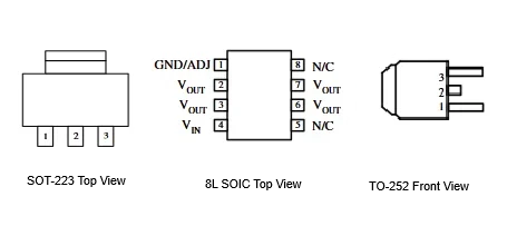
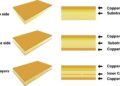
AMS1117 in three common packages
(Alt text: Pinout of the AMS1117 in three common packages)
[Link to source of image]
The AMS1117 is most commonly found in the SOT-223 surface-mount package, though it is also available in TO-252 (DPAK) and SOIC-8 formats. Because it is a linear regulator, the physical tab is connected to the output pin (Vout) to help conduct heat into the PCB copper.
- Pin 1 (ADJ / GND): In fixed versions, this pin connects to ground. In the adjustable version, it connects to the resistor divider used to set the voltage.
- Pin 2 (Vout): The regulated output voltage. This pin is also electrically connected to the large metal tab.
- Pin 3 (Vin): The unregulated input voltage.
Internal Protection Features
The AMS1117 Datasheet details the internal safety mechanisms that prevent the device from failing under stress.
- Thermal Shutdown: The IC includes on-chip thermal limiting circuitry. If the internal junction temperature reaches approximately 150 degrees Celsius, the device will shut down the output to prevent permanent damage.
- Current Limiting: The AMS1117 includes short-circuit protection. It limits the output current to a safe level (typically around 1.1A to 1.5A) if the load attempts to draw more than the rated capacity.
Heat Dissipation and PCB Layout
The primary limitation of any linear regulator is heat. A linear regulator drops voltage by converting the “excess” energy into thermal energy. You can calculate the power dissipated as heat using the following formula:
Power (Watts) = (Vin – Vout) * Iout
For example, if you drop 5V to 3.3V at 500mA, the IC generates 0.85 Watts of heat. In a small SOT-223 package, this can quickly trigger the internal thermal shutdown if the layout is poor. To manage this, designers can:
- Use Copper Pours: Create a large copper area as a heat sink connected to the Pin 2/Tab pad.
- Thermal Vias: Use vias to connect the top-side copper pour to a ground plane or a secondary pour on the bottom layer to increase the surface area for cooling.
Stability and Capacitor Selection
The AMS1117 requires external capacitors to stay stable and prevent oscillations.
- Input Capacitor: A 10uF tantalum or electrolytic capacitor is recommended to filter the input supply.
- Output Capacitor: A 22uF tantalum capacitor is typically required on the output. While modern ceramic capacitors are popular, they have very low equivalent series resistance (ESR). Some versions of the 1117 require a specific ESR of a tantalum capacitor to maintain stability. If you use a ceramic capacitor, check the specific manufacturer’s notes in the datasheet regarding ESR requirements.
Typical Applications
The most common use of the AMS1117 is 5V-to-3.3V conversion. This allows a device to take power from, for example, a USB port (5V) and regulate it down for 3.3V microcontrollers or Wi-Fi chips. It is also used in battery-powered devices that require a stable voltage as the battery discharges, provided the battery voltage remains at least 1.1V above the regulated target.
The AMS1117 is a reliable, low-cost solution for point-of-load voltage regulation. By paying close attention to the dropout voltage and thermal dissipation limits, you can ensure your logic circuits receive clean, stable power.
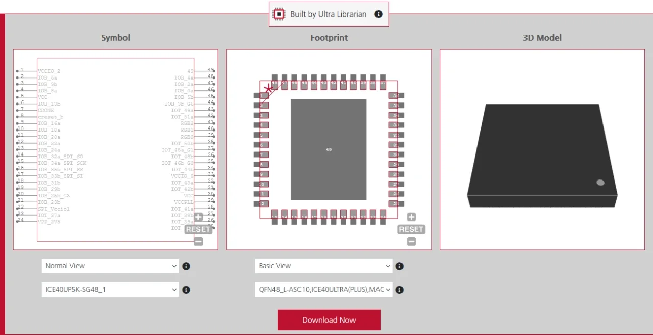
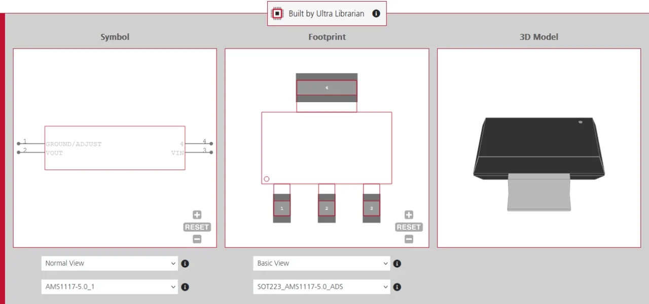
If you need to add this regulator to your design, Ultra Librarian provides verified CAD models featured in the AMS1117 datasheet. You can download the schematic symbol, PCB footprint, and 3D model for all popular ECAD applications.
Working with Ultra Librarian sets your team up for success, ensuring streamlined and error-free design, production, and sourcing. Register today for free.



 If you’re looking for any of our component footprints or models, we have readily available and free options for you and your design team. Search our library for the solution you’ve been looking for.