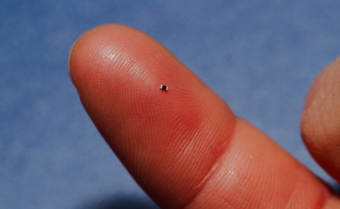
In modern electronics, miniaturization continues to drive component selection and system design. As engineers pack more functionality into smaller devices like wearables, IoT sensors, and mobile phones, the physical size of passive components shrinks accordingly. Among the vast array of Surface Mount Device (SMD) packages, the 0402 package has become a widely adopted standard for high-density printed circuit board (PCB) designs.
This guide provides an overview of the 0402 package footprint. It includes the often-confusing naming conventions, details the physical dimensions, reviews common 0402-package passive components, including resistors, capacitors, and inductors, and provides actionable advice on designing footprint to prevent common manufacturing defects.
Decoding the 0402 Name: Imperial vs. Metric
One of the most common mistakes an engineer can make when specifying components or designing a PCB is confusing the imperial and metric naming conventions for SMD packages.
The name “0402” refers to the approximate physical dimensions of the component. However, the electronics industry uses two different measuring systems concurrently.
- 0402 (Imperial): This is the most common usage in North America. It denotes a component approximately 0.04 inches long by 0.02 inches wide.
- 0402 (Metric): In the metric system, a 0402 package refers to a component that is 0.4 mm long by 0.2 mm wide. (The imperial equivalent of this tiny metric package is 01005).
(Note: For the remainder of this article, we will refer to the standard Imperial 0402 package, which is equivalent to the Metric 1005 package.)
0402 Package Footprint Dimensions and Specifications
The Imperial 0402 package is incredibly small, yet large enough to be handled reliably by modern automated pick-and-place machines. Below are the standard dimensions and typical ratings of common resistor package sizes.
SMD Resistor Sizes and Codes
| Imperial Code | Metric Code | Length (in) | Length (mm) | Width (in) | Width (mm) | Height (in) | Height (mm) | Power (W) |
| 0201 | 0603 | 0.024 | 0.60 | 0.012 | 0.30 | 0.010 | 0.25 | 1/20 |
| 0402 | 1005 | 0.040 | 1.00 | 0.020 | 0.50 | 0.014 | 0.35 | 1/16 or 1/10 |
| 0603 | 1608 | 0.060 | 1.55 | 0.030 | 0.85 | 0.018 | 0.45 | 1/10 |
| 0805 | 2012 | 0.080 | 2.00 | 0.050 | 1.20 | 0.018 | 0.45 | 1/8 |
| 1206 | 3216 | 0.120 | 3.20 | 0.060 | 1.60 | 0.022 | 0.55 | 1/4 |
| 1210 | 3225 | 0.120 | 3.20 | 0.100 | 2.50 | 0.022 | 0.55 | 1/2 |
| 1812 | 3246 | 0.120 | 3.20 | 0.180 | 4.60 | 0.022 | 0.55 | 1 |
| 2010 | 5025 | 0.200 | 5.00 | 0.100 | 2.50 | 0.024 | 0.60 | 3/4 |
| 2512 | 6332 | 0.250 | 6.30 | 0.120 | 3.20 | 0.024 | 0.60 | 1 |
Note: Exact dimensions and tolerances will vary slightly by manufacturer and component type (especially height for high-capacitance MLCCs). Always check the specific manufacturer’s datasheet.
Beyond Resistors: Capacitors and Inductors
The 0402 package footprint is the standard size for a vast array of passive components. Because the physical volume is restricted, the electrical capacity is also limited.
- 0402 Resistors: Due to the small surface area, the power dissipation rating is typically limited to 1/16 W (0.063 W) or 1/10 W (0.1 W). You cannot run high currents through these parts without risking thermal failure.
- 0402 Capacitors: Advances in ceramic technology have enabled multi-layer ceramic capacitors (MLCCs) to deliver significant capacitance in this package. You can find 0402 capacitors up to 1 uF or 2.2 uF at lower voltage ratings (e.g., 6.3 V or 10 V). As voltage ratings increase, the available capacitance decreases significantly because thicker dielectric layers are required. While 25 V and 50 V variants are available, their capacitance is typically limited to the nanofarad (nF) range, with only a small selection of higher-capacitance parts.
- 0402 Inductors: Often used for radio frequency (RF) matching or high-frequency filtering. Their inductance values are usually limited to the nano-henry (nH) range, and the thin internal wire strictly limits their DC current-carrying capacity.
- Other 0402 Components: While the 0402 package is primarily associated with passive components, a limited number of active devices are also available in similar footprints. Examples include LEDs, ESD protection diodes, RF diodes, and certain transistor arrays. However, integrated circuits are rarely packaged in true 0402 dimensions because the footprint is generally too small to accommodate the required number of electrical connections and provide adequate heat dissipation.
Designing the 0402 Footprint
Although the 0402 component is tiny, the copper pads (land pattern) you draw on your PCB must be significantly larger to accommodate manufacturing tolerances and the solder fillet.
There is no single “perfect” land pattern. The size of the pads depends heavily on the assembly process. The industry standard for footprint design is IPC-7351C, which defines three density levels for land patterns:
- Density Level A (Maximum): Provides the most robust solder joint. Best for low-density boards or harsh environments subject to high vibration.
- Density Level B (Nominal): The most common standard. Balances a strong solder joint with efficient use of board space.
- Density Level C (Least): Used for ultra-high-density boards (like smartphones). The pads are only slightly larger than the component terminals, increasing manufacturing difficulty.
The Threat of Tombstoning
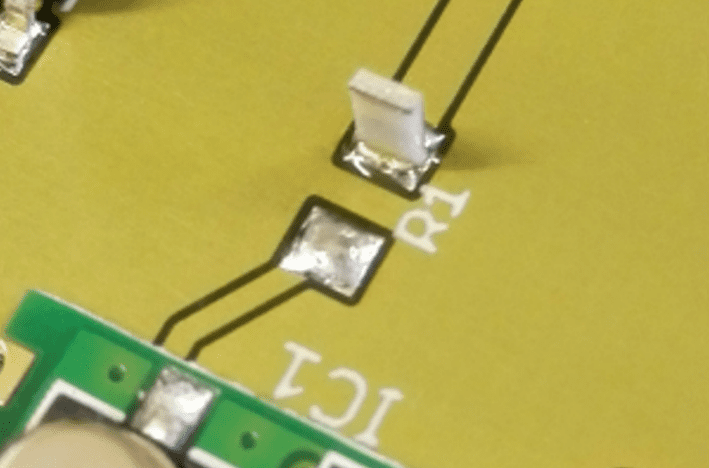
The most notorious manufacturing defect associated with 0402 components is tombstoning (also known as the Manhattan effect). Tombstoning occurs during reflow soldering when the solder paste on one pad melts before that on the other. The surface tension of the molten solder on the melted pad physically pulls the component upright, standing it on end like a tombstone, and breaking the electrical connection on the other side.
How to Prevent Tombstoning in 0402 Layouts
Tombstoning is almost entirely a thermal management and footprint design issue. To prevent it, PCB designers should ensure both pads heat up at the exact same rate during reflow:
- Equal Solder Paste Volume: Ensure the land pattern pads are perfectly symmetrical. If one pad is larger than the other, the larger pad will take longer to heat up, causing a thermal imbalance.
- Thermal Reliefs on Planes: If one pad connects to a thin signal trace and the other connects directly to a massive, solid ground plane, the ground plane acts as a heatsink. The signal pad will melt first, pulling the component up. Always use thermal relief spokes when connecting a 0402 pad to a large copper pour or plane.
- Symmetrical Routing: Try to route traces of identical width into both pads of the 0402 component. If one pad has a 5-mil trace entering it and the other has a 20-mil trace, the wider trace will draw heat away faster.
- Use Verified Footprints: Using a land pattern that strictly adheres to IPC-7351C standards guarantees that the pad geometry is optimized to prevent surface tension imbalances.
Start Your Design with Confidence
Working with tiny components like the 0402 package footprint requires massive attention to detail. Ultra Librarian helps by compiling all your sourcing and CAD information in one place. By downloading verified footprints directly in the native format of your ECAD software (Altium, OrCAD, KiCad, etc.), you eliminate the risk of tombstoning and footprint mismatch errors.
Set your team up for first-pass success. Register today for free and download the precise, IPC-compliant models you need for your next layout.
Working with Ultra Librarian sets your team up for success, ensuring streamlined, error-free design, production, and sourcing. Register today for free.

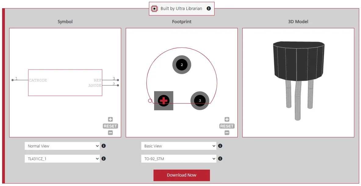
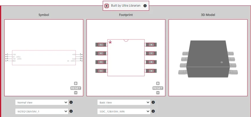
 If you’re looking for any of our component footprints or models, we have readily available and free options for you and your design team. Search our library for the solution you’ve been looking for.