
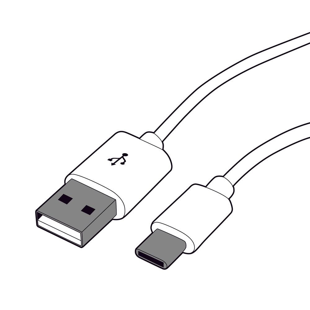
The average person has a lot of electronic devices, and most of them have different types of cords. People are familiar with large USB (USB-A) cords, micro USB (USB-B) cords, and many other cord types, but a universal type of cord wasn’t a possibility until the USB-C. The USB cord, which is similar, but more rounded than the common type A raises the bar for electronics connectivity. Not only does the USB-C allow for faster data transmission/reception (TX/RX), but also greatly advances charging of common devices like laptops and cellular phones. Effective USB-C power delivery circuit design requires understanding the connectors and cables that enable the Leveraging these capabilities.
USB-C Power Delivery Circuit Features and Applications
Important features of USB-C power delivery circuits include the following.
The functionalities and capabilities above have enabled a wide range of implementations for USB-C PD circuits, as listed below.
Common Applications for USB-C Power Delivery Circuits
- Computing peripherals
- Hard disk drives (HDDs)
- Laptop power supply/charger
- Power delivery and pass-through networks within computers and laptops
In order to design and develop systems to take advantage of USB-C PD features, it is necessary to understand the foundation on which it relies, which is USB-C.
What Is USB-C?
USB-C is a hardware standard developed by the USB Implementers Forum (USB-IF). USB-IF is comprised of companies working together to develop USB standards, define compliance testing requirements, and promote the advancement of the technology. Standards are constantly being improved upon, and a USB4 specification was published in late 2019.
USB-C Development Objectives
USB-C cables differ from previously developed cables, pioneering technology that is a key component of the USB4 specification. For example, transfer rates can extend up to 400 gigabytes of data per second (GBps), and the USB4 specification lays the groundwork for that becoming standard. USB-C is meant to usher in a new era of connector cords and data transfer, much simpler and faster than previous technologies.
USB-C cables are designed for ease of use, and they directly address some of the usability headaches annoying consumers for 20 years. Connectors have an oval shape and a significantly simpler internal structure within the metal casing on each end. This means USB-C cords can fit into their ports in any orientation, and the need to flip a USB cable into the proper orientation is a thing of the past.
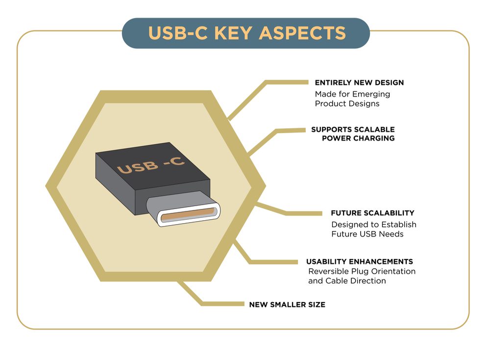
The simpler structure inside the casing also makes it easier to align a cable with its port. Although the end casing is slightly thicker than other USB cords, its overall size is smaller. A USB-C cable also has the same casing on either end, which means the cord is reversible and power transfer is equally efficient regardless of how the cord is plugged in.
What Is USB-C Power Delivery?
USB-C power delivery (USB-PD) is a new technology in certain USB-C cords, supporting charging technology faster than the charging hardware which comes standard with many devices. Anything below a USB 3 provides about 5 volts of charge to devices, and cannot handle major fluctuations well, even though USB cords contain voltage regulators. USB-C cables can handle up to 20 volts and 5 amperes of current, which is 4 times the previous voltage standard, and 10 times the previous amperage standard. USB-C power delivery is even more scalable than this, however, and it can transfer up to 100 watts safely. Most smartphones can’t handle such a high wattage; but other devices can, which is where the true potential of USB-C power delivery lies.
USB-C power delivery is not the only fast charging, data transfer technology available. An organization called Qualcomm has a competing version, and unlike USB-PD, this version is usable with USB-A, USB-B, and USB-C cords. The Qualcomm standard can’t transfer the same high potential voltage as USB-PD, but it’s supported by some major device makers, so it’s possible both standards could become common. If USB-A and USB-B connector cables ever become completely obsolete, USB-PD would be a clear frontrunner. However, as long as multiple USB types exist, the possibility for multiple fast charging and data transfer standards remains.
PCB Design for USB-C PD
Many companies have begun utilizing USB-C power delivery technology (also called USB-PD) and the development of compliant devices will continue to increase. Regardless of who supplies the ports and standards, the obvious speed, efficiency, and usability benefits of USB-C cords and USB-C power delivery should influence some major changes to the electronics landscape. The high voltage potential of USB-C power delivery will mean charging a computer could be as simple as plugging in a single cable in the near future—no more bulky transformers required.
When designing circuit boards for USB-PD integration, it is important to follow guidelines, as listed below.
Following the guidelines will help you to design and develop USB-C PD circuits that meet your performance objectives and adhere to industry standards.
If you’re looking for CAD models for common components or important design information about USB-C power delivery circuits, Ultra Librarian helps by compiling all your sourcing and CAD information in one place.
Working with Ultra Librarian sets up your team for success to ensure streamlined and error-free design, production, and sourcing. Register today for free.


")