Not all user input needs to be applied mechanically—mechanical switches and buttons are not going to disappear from every electronic system, but sometimes you need electrical actuation in a system to provide switching behavior. Relays and transistors are the two most common electrically actuated switches used in electronics; however, they are not perfect replacements for each other.
When you’re deciding whether to use relays vs. transistors, what criteria should you use to make your decision? No matter which of these components you want to use, you can find the component data and CAD models you need with an electronic parts search engine. Let’s look at how to select and import relays and transistors as switching elements for your next design.
Relays vs. Transistors: Their Unique Characteristics
Relays and transistors are multi-terminal devices that provide switching functions. In both components, switching is actuated by applying an electrical voltage/current, but the exact mechanism by which current is allowed to flow through the switch is different in relays vs. transistors.
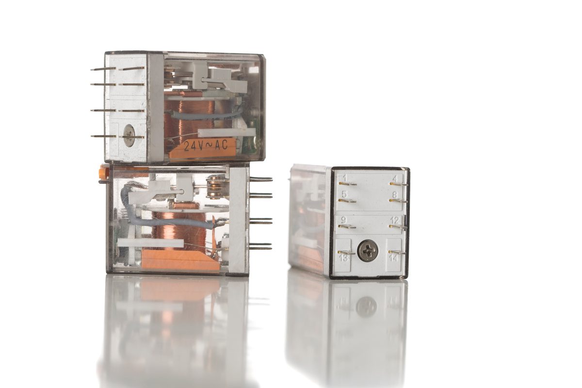
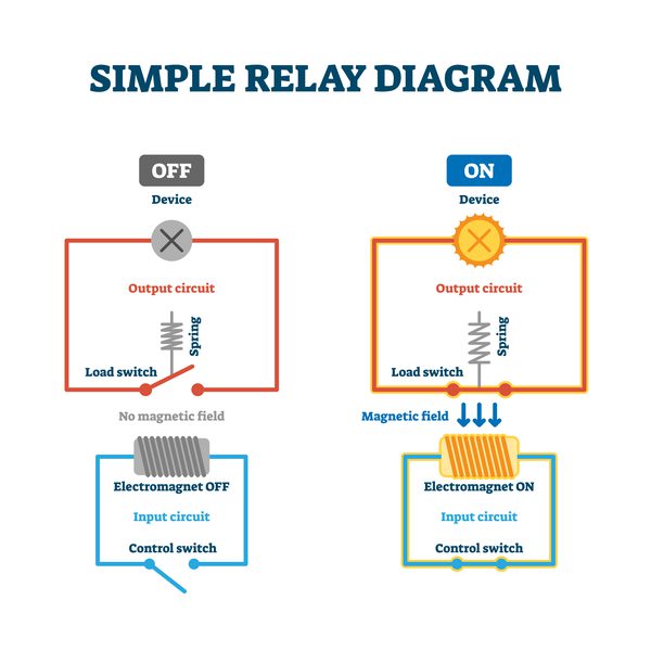
- Relay switching: A relay is a mechanical switch triggered by using an electric current to generate a magnetic field near an armature. A magnetic field is generated in a coil, which pulls the mechanical switch armature closed or pushes it open.
- Transistor switching: Transistors are semiconductor devices, and the electrical conductivity of the conduction channel is modulated by applying a voltage (for FETs) or current (for bipolar transistors) to the third terminal.
Because these components allow current to flow via different mechanisms, they also have different switching characteristics. They are also designed for use in different situations, depending on the nature of the load being connected to the device and the power source. The table below shows a comparison of the various applications for relays vs. transistors.
| Application area and specification | Relay | Transistor |
| Power level | Can be used with very high voltages and currents that would destroy transistors. | Power transistors can have up to ~100 V breakdown voltages and supply dozens of amps. |
| Load type | Can be used to supply power to a range of loads. | Power delivery to the load needs to be carefully designed so the transistor does not saturate. |
| Switching frequency | Slow switching, not intended for a large number of switching events or repeated switching. | Can be used with very fast switching at high frequency (e.g., ~100 kHz in power supplies or ~2 GHz in CPUs). |
| ON-state resistance | Very low; equal to the DC resistance of the electrical contacts. | Down to ~mOhm for large power MOSFETs. |
To better understand why relays vs. transistors are generally used in different applications, it helps to understand their electrical behavior during switching and when these devices reach a steady ON or OFF state.
Transient Response
This is one area where relays are really distinguished from transistors. Because relays are often used in high voltage systems, the armature has to cover a large distance as it swings closed, so the switching time is quite long. The typical switching time for a relay is tens of milliseconds, whereas the switching time for large power transistors can reach nanoseconds (over a factor 1 million faster). Just for comparison, extremely fast transistor switching happens in high-speed components like CPUs/GPUs/MPUs and in high-speed signaling protocols like PCIe and DDR. Therefore, if very fast switching is needed, a transistor is the best choice.
Since transistors can be used to switch power flowing to ICs, they are essentially driving capacitive loads and there is a slightly delayed response seen at the IC pin due to its input capacitance. Contrast this with a relay; the relay’s coil inductance generates a back EMF surge during switching that can destroy integrated circuits. This back EMF is normally damped with a flyback diode to prevent damage to other components in the system.
Isolation
The activating circuit in a relay is galvanically isolated from the energized side of the relay, which provides a major level of safety when relays are used for switching high voltages. In contrast, a transistor does not have any isolation, and an ESD event at one terminal can propagate to the two other terminals. Transistors used in high power systems that need some ESD protection will require some extra components for user protection and to ensure circuits are not damaged.
DC and AC Power
A relay can be used with AC or DC power over a very broad range of power levels. A transistor is generally meant to be used with DC power or digital signals, but they can be used with AC signals as well. However, a transistor must be carefully designed to operate in its linear range to prevent the transferred AC signal from clipping and producing harmonic distortion. For this reason, transistors are less desirable for use in high power AC systems, but they are still useful as analog components generally, as long as they are operating in the linear range.
Lifetime
Relays are not meant to be switched repeatedly, as their electrical contacts will wear out over time. In contrast, a transistor has no moving parts, so it will have an exceedingly long lifetime and can be switched repeatedly without experiencing wear as long as it is not driven beyond its absolute maximum ratings. This is why transistors are used as switching elements in switched-mode power supplies and power converters.
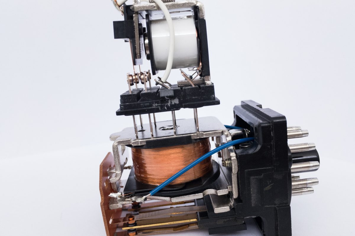
Over time, the contacts in the top-left portion of this image will wear out due to friction and arcing
If you need to find and compare relays vs. transistors for your next design, you can find component specifications and CAD models for your parts with the electronics search engine features in Ultra Librarian. You’ll have access to verified CAD models that can be imported into popular ECAD applications, and you can view sourcing information from worldwide distributors.
Working with Ultra Librarian sets up your team for success to ensure any design is going through production and validation with accurate models and footprints to work from. Register today for free.