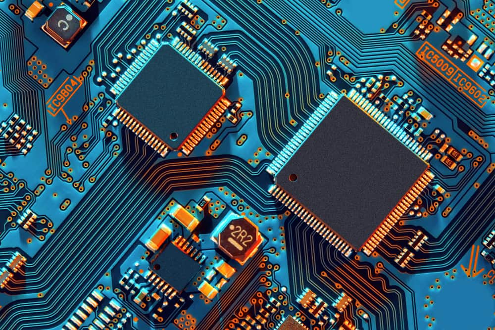
Older through-hole components were physically large enough to display full manufacturer names and electrical ratings directly on the packaging. In contrast, modern surface-mount technology has reduced parts to microscopic sizes, where engineers must rely almost entirely on shorthand markings. As a result, tracking the many abbreviations scattered across schematics and component bodies requires both patience and experience.
Recognizing common PCB component codes is a basic skill for hardware engineers, technicians, and layout designers alike. This guide serves as a detailed reference manual that will help you identify reference designators, decode surface-mount device markings, and understand protocol acronyms listed in technical datasheets.
The Ultimate Cheat Sheet: Common PCB Component Codes
Before examining specific component categories, the table below outlines the standard reference designators printed on the silkscreen layer of a circuit board. You will encounter these letters on almost every modern layout.
Common PCB Reference Designators
| Reference Designator | Component Type | General Description |
| U or IC | Integrated Circuit | Complex silicon chips and microcontrollers. |
| R | Resistor | Limits electrical current flow. |
| C | Capacitor | Stores and releases electrical energy. |
| L | Inductor | Resists rapid changes in current flow. |
| D or CR | Diode | Allows current to flow in one specific direction. |
| Q | Transistor | Amplifies or switches electrical signals. |
| J or P | Connector | Connects external cables or hardware to the board. |
| TP | Test Point | A designated copper pad for measuring electrical signals. |
| Y or X | Crystal Oscillator | Generates precise timing clock signals. |
| F | Fuse | Breaks the circuit physically during an overcurrent event. |
| SW | Switch | Manually connects or disconnects a circuit path. |
Want a printable version? Download the free PCB Component Codes cheat sheet to keep this reference at your workstation or share with your team.
Making Sense of Reference Designators
Reference designators act as map coordinates for your layout. They are printed directly on the top or bottom layers of the circuit board using silkscreen ink. Every single component receives a unique designator.
The code usually combines a letter and a number. For instance, if you see “R12” printed next to a small part, that exact text tells you it is the twelfth resistor listed in the bill of materials. Larger boards might contain hundreds of resistors. Therefore, clear labeling impacts how fast an assembly team can assemble the hardware.
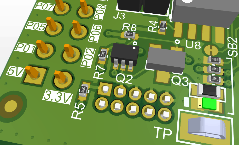
These reference codes trace directly back to the original schematic, which allows engineers to troubleshoot hardware efficiently. If a voltage regulator runs unusually hot, a technician can spot the “U4” marking on the board, find U4 in the schematic, and instantly identify the exact manufacturer part number.
Interestingly, you might notice missing numbers in a sequence. You might see C1, C2, and C4, but no C3 anywhere on the layout. Missing reference numbers usually occur because a designer deleted a part during the engineering process. Rather than renaming every single capacitor on the board, the designer simply left the numerical gap. Leaving gaps is completely normal as it saves significant time during layout revisions.
How to Decode Component Markings
Often, you will find components that lack full part numbers. Small Surface Mount Devices (SMDs) simply lack the physical surface area to fit a long manufacturer part number. Consequently, semiconductor manufacturers apply short, cryptic alphanumeric sequences, known as SMD marking codes.
Decoding these tiny markings often confuses beginners. Occasionally, two entirely different components from different manufacturers will share the exact same marking code, which can get frustrating. However, you can usually solve the mystery by measuring the physical package. To accurately decode SMD marking codes, follow these specific steps:
- Identify the physical package style. Look at the general shape to determine if it is a SOT-23, an SC-70, or an SMA package.
- Count the exact number of pins.
- Locate the pin 1 indicator. Manufacturers often use a tiny dimple, a laser-etched dot, or a chamfered edge to mark the first pin.
- Cross-reference the marking code. Check the short marking code against the package type using an online SMD code database or the manufacturer’s official datasheet.
Modern chips use precise laser etching to apply these markings. Older parts relied heavily on printed white ink. Many modern passive components are microscopic. For example, 0402- or 0201-sized ceramic capacitors are so small that they have no printed codes whatsoever. When dealing with completely blank parts, engineers must rely entirely on the surrounding common PCB component codes printed on the actual bare board.
Electronics companies frequently add date codes, factory tracking symbols, or lot numbers alongside the main marking. Understanding exactly which text string represents the actual part number helps engineers avoid purchasing mistakes. Buying the wrong operational amplifier because of a misread lot code wastes valuable development time.
Deciphering Component Packages and Footprints
Datasheets contain specific package codes that tie directly to the physical dimensions of a component. While these specific codes rarely appear on the physical chips themselves, they dictate the exact land pattern required for the printed circuit board footprint.
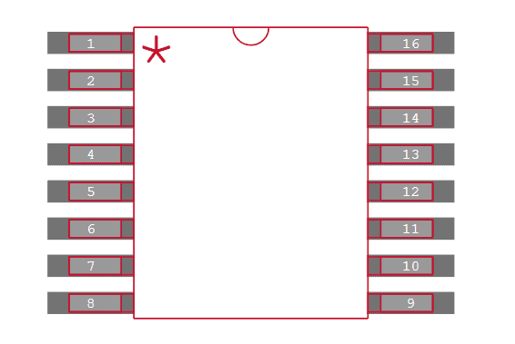
Standardized packages follow dimensional guidelines set by the Association Connection Electronics Industries (commonly referred to as the IPC, as per their prior name). For surface-mount components, engineers refer to the IPC-7351B standard. Through-hole components use the IPC-7251 standards. If a layout designer selects an SOIC-8 package, they know exactly how wide the copper pads need to be.
The table below highlights a few standard passive component package sizes.
Standard SMD Package Size Codes
| Imperial Code | Metric Code | Dimensions (Length x Width in mm) |
| 1206 | 3216 | 3.2 x 1.6 |
| 0805 | 2012 | 2.0 x 1.25 |
| 0603 | 1608 | 1.6 x 0.8 |
| 0402 | 1005 | 1.0 x 0.5 |
| 0201 | 0603 | 0.6 x 0.3 |
Adhering to standardized package codes ensures that the physical part fits correctly onto the bare board during final assembly, as incorrect pad sizes lead to manufacturing defects. A classic example is tombstoning, where a tiny resistor stands upright on one end during soldering.
Digital Protocols on Component Datasheets
Reviewing a modern datasheet introduces another layer of alphabet soup. Semiconductors communicate via specific digital protocols. These acronyms define how digital data moves between different silicon chips. Here are several standard signaling interfaces you will regularly encounter:
- I2C (Inter-Integrated Circuit): A two-wire serial bus protocol. Host controllers use I2C to communicate with peripheral sensors at lower speeds.
- I2S (Inter-IC Sound): A serial bus interface. Audio engineers use I2S to connect multiple digital audio devices together.
- SPI (Serial Peripheral Interface): A synchronous serial communication interface. SPI supports full-duplex data transfer, meaning the interface can send and receive data simultaneously over separate lines.
- UART (Universal Asynchronous Receiver-Transmitter): A serial communication interface that transmits data one bit at a time between two devices over dedicated TX and RX lines, without requiring a shared clock signal.
- GPIO (General-Purpose Input/Output): An uncommitted digital signal pin on an integrated circuit. Engineers configure GPIO pins through software to act as either input readers or output drivers.
- CAN (Controller Area Network): A highly reliable bus standard designed originally for automotive applications. CAN allows microcontrollers and devices to communicate directly without requiring a central host computer.
- LIN (Local Interconnect Network): A cheaper, slower alternative to CAN. Automotive engineers use LIN for simple tasks, such as adjusting power windows or reading seat sensors.
- Ethernet: The standard protocol for wired local area networks. Ethernet components handle high-speed data transmission over physical copper cables or fiber-optic links.
- PCIe (Peripheral Component Interconnect Express): A high-speed serial computer expansion bus standard. High-performance computing boards heavily rely on PCIe for massive data throughput between graphics cards, network adapters, and solid-state drives.
- USB (Universal Serial Bus): A widely adopted differential interface. USB components manage communication and power-supply negotiation between host computers and external peripheral devices.
Understanding these protocol acronyms helps designers select the correct microcontrollers. It also aids in planning proper routing strategies for specific hardware applications.
Find Your Parts with Common PCB Component Codes
Keeping track of thousands of tiny parts requires significant effort. Whether you search by manufacturer part number, electrical specifications, or standard signaling protocols, finding accurate CAD data takes time. Hardware designers shouldn’t waste valuable hours drawing complicated footprints from scratch.
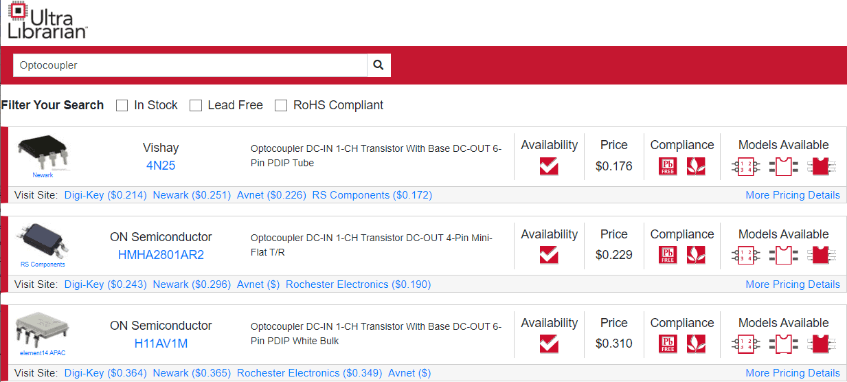
To simplify the engineering workflow, Ultra Librarian provides a massive cloud-based electronic component library. By entering common PCB component codes directly into our search engine, you instantly gain access to verified schematic symbols. Before you dive in, grab the free printable PCB Component Code Reference Chart as a quick-reference companion for your bench or next design review. You also receive accurate printed circuit board footprints and verified 3D models. Every provided model exports natively to major electronic design automation software.
Skip the tedious manual data entry and start designing your hardware faster. When you use Ultra Librarian, you’ll have access to datasheets, technical specifications, CAD data, and verified 3D models from worldwide distributors that can be imported into popular ECAD applications. After learning about common PCB component codes, register with Ultra Librarian to find the exact electronic components your next project requires.
Working with Ultra Librarian sets your team up for success, ensuring streamlined and error-free design, production, and sourcing. Register today for free.


 If you’re looking for any of our component footprints or models, we have readily available and free options for you and your design team. Search our library for the solution you’ve been looking for.