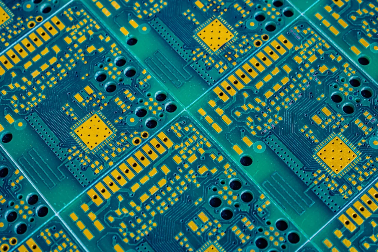
Designing a printed circuit board (PCB) can feel a bit like building a layered cake: each layer has a specific job, and just as a cake collapses when its layers are stacked in the wrong order, a board fails if its internal arrangement is off. Using a PCB stack-up design guide allows the engineer to plan a layer arrangement that serves as the foundation for modern electronics.
Get the stack-up wrong, and no amount of clever routing later will save the board. Think of it as choosing the wrong pill in The Matrix. Once the foundation is set, you’re living with the consequences. That’s why the internal structure needs to be locked in before a single trace gets routed. The following text explores the mechanics behind layer configurations, material science, and high-speed routing strategies to keep the designs functioning perfectly.
Core Principles of a PCB Stack-Up Design Guide
Any multi-layer board requires a defined arrangement of signal, ground, and power planes. A clear PCB stack-up design guide dictates how the copper planes interact. The planes control electromagnetic fields and provide defined return paths for electrical currents. Consider the specific advantages of placing planes strategically:
- Tight Return Paths: Placing a fast signal layer next to a solid ground plane reduces trace-loop radiation by roughly 10 decibels. When the physical distance between the signal trace and the return path decreases, the loop inductance drops fast.
- Thermal Management: Heavy ground layers draw heat away from hot chips, serving as effective heat sinks. As a result, the metal planes solve both an electrical and a thermal problem simultaneously.
- Voltage Stability: Ground and power planes advantageously act as decent capacitors, depending on stack height. The metal sheets stabilize voltage delivery across the entire board.
A standard four-layer layout often follows a Signal-Ground-Power-Signal sequence. Further, the solid copper blocks electromagnetic noise between the top routing layer and the bottom routing layer. Accordingly, complex layouts require more layers to isolate sensitive nets.
For example, a standard six-layer build typically uses a Signal-Ground-Signal-Power-Ground-Signal arrangement. Here, the inner signal layers sit buried between solid reference planes. The planes heavily shield the internal traces from outside noise. Placing signal traces close to reference planes tightly couples the electric fields. Therefore, the fields stay contained rather than spilling over into neighboring circuits.
Material Selection: Dielectrics and Copper Weight
The substrate you pick matters just as much as the schematic, sometimes more. The dielectric constant (Dk) and dissipation factor (Df) determine how fast signals travel and how much energy the signals lose. High-frequency boards need highly stable dielectrics. Instead, designers match the specific substrate chemistry to the operating frequency.
Standard FR-4 glass-epoxy works perfectly fine for basic digital logic. The FR-4 material typically has a Dk of around 4.2 to 4.5 and a Df of near 0.02. However, FR-4 struggles above a few gigahertz. High-frequency signals simply lose too much strength as they travel through the lossy fiberglass weave.
High-speed laminates like Rogers RO4350B step in for demanding radio frequency (RF) applications. The RO4350B material maintains a tight Dk of 3.48 at 10 GHz and a remarkably low Df of 0.0037. Such a low loss tangent keeps high-frequency signals crisp and clear over long transmission lines. Notably, advanced FR-4 blends like Isola 370HR offer a fantastic middle ground. The Isola laminate provides high thermal reliability for intense lead-free manufacturing processes while keeping raw material costs reasonable.
Manufacturers like TE Connectivity and Molex also offer connectors and interconnect components rated for the same high-Tg and high-frequency material systems, so stack-up decisions often ripple into component selection.
Common PCB Substrate Materials and Electrical Properties
| Material | Classification | Dk (Dielectric Constant) | Df (Dissipation Factor) |
| Standard FR-4 | Basic Digital | 4.2 – 4.5 | ~0.020 |
| Rogers RO4350B | RF / High-Speed | 3.48 | 0.0037 |
| Isola 370HR | High-Tg FR-4 | 4.04 | 0.021 |
Glass transition temperature (Tg) is another vital metric. The specific metric indicates the temperature at which the rigid substrate becomes soft and rubbery. Standard FR-4 features a Tg around 135 °C.
When a board passes through a lead-free reflow oven, the extreme heat pushes basic materials beyond their mechanical limits. The physical expansion stretches the internal copper plating inside the vias. If the metal stretches too far, the via barrel cracks, creating an open circuit and ruining the entire board. As a result, high-heat manufacturing demands substrates with a Tg of 170 °C or higher.
Copper thickness also matters immensely for signal integrity. Manufacturers measure copper weight in ounces per square foot. Engineers typically select from three standard thickness categories:
- Standard Weight (1 oz / 35 µm): Default choice for most digital boards, offering a solid balance between current capacity and trace etching resolution.
- Heavy Copper (2 oz / 70 µm): Supports higher current loads and improves thermal dissipation in high-power applications. However, heavy copper limits the fab house’s ability to etch fine traces.
- Light Copper (½ oz / 17.5 µm): Makes routing tiny traces much easier. The thin layer supports fine-pitch ball grid arrays (BGAs) and precise impedance calculations for high-speed lines.
This is a common spec for power-dense designs using components from manufacturers such as Texas Instruments or Infineon.
Symmetry and the Prevention of Board Warpage
If a board isn’t balanced, factory heat will bend it. A balanced build keeps the physical forces equal. For instance, imagine stretching a rubber band across a piece of thin cardboard; if the tension only pulls on one side, the cardboard bends immediately. Circuit boards behave identically.
During the high-heat lamination process, dissimilar materials expand at completely different rates. When the hot board cools down, the metal and fiberglass shrink. If the copper density is uneven, the board curves violently. To reduce board warpage during manufacturing, engineers maintain symmetry across several structural parameters:
- Z-Axis Mirroring: A balanced design mirrors the layer types from the top half of the board to the bottom half. If layer two is a solid ground plane with 1 oz copper, the second-to-last layer should also be a solid plane with 1 oz copper.
- Dielectric Thickness Matching: The prepreg and core materials share identical thicknesses on opposite sides of the center axis. The physical symmetry ensures the mechanical tension pulls equally in both directions during cooling.
- Horizontal Copper Distribution: If one side of a layer features heavy copper pours while the other side sits mostly empty, the local area twists when heated. Designers often add dead copper polygons to sparse areas.
Such a technique balances the metal volume across the entire horizontal plane. Consequently, the internal mechanical stresses cancel each other out, keeping the final assembled product flat.
High-Speed Routing and Crosstalk Mitigation Strategies
High-speed digital signals flip between voltage levels fast. We’re talking razor-thin rise and fall times between “low” and “high.” However, rapid changes in the signal amplitude generate noisy electromagnetic fields that easily couple into adjacent traces. Referencing a strict PCB stack-up design guide helps mitigate the dangerous interactions. Managing aggressive noise requires strict routing disciplines.
Consider the following layout methods:
- Reference Plane Integrity: High-speed traces generally need to route over a continuous, unbroken reference plane. Crossing a split or a physical void in the ground plane forces the return current to take a wide detour around the gap. Such a detour creates a massive loop antenna, spreading radiation everywhere and failing electromagnetic compatibility (EMC) compliance tests.
- Controlled Layer Transitions: When a signal jumps from the top layer to the bottom layer through a via, the return current also changes reference planes. Placing a ground-to-ground stitching via right next to the via gives the high-frequency return current a direct, low-impedance path.
- Orthogonal Routing: When routing signals on adjacent inner layers, run the copper traces perpendicular to each other. For example, if layer three runs horizontally, layer four should run vertically. Such a strategy drastically reduces broadside crosstalk between the parallel layers.
- Trace Spacing Rules: Spacing traces properly limits interference. A common rule suggests keeping parallel traces separated by at least three times the trace width. The specific spacing rule drastically reduces magnetic coupling between neighboring lines.
Impedance matching ties all the mentioned parameters together. The trace width, copper thickness, and distance to the reference plane directly determine the trace impedance. Keeping a consistent 50-ohm single-ended or 100-ohm differential impedance prevents severe signal reflections. So, if the physical geometry changes mid-route, part of the signal bounces right back to the source chip.
Planning a successful board starts with a dependable PCB stack-up design guide, but finishing the job requires verified component data. Ultra Librarian integrates directly with popular ECAD applications, supplying engineers with millions of accurate CAD models and footprints. Further, the database links directly with worldwide distributors, ensuring the chosen parts remain in stock. Search Ultra Librarian today to find exactly what the next complex project needs.
Working with Ultra Librarian sets your team up for success by ensuring streamlined, error-free design, production, and sourcing. Register today for free.


 If you’re looking for any of our component footprints or models, we have readily available and free options for you and your design team. Search our library for the solution you’ve been looking for.