In today’s low-voltage electronics landscape, you generally have two options for diodes: pn diodes and Schottky diodes. These two diodes both provide rectifying action by limiting high-conductance current flow in a single direction determined by the voltage drop across the component. For example, in a power system, a Schottky diode will ensure a system has the rectification required to convert AC power or switching power into a stable DC voltage.
Like many other components on the market, the 1N5822 Schottky diode is a generic component that multiple manufacturers produce. Because of the universality of the 1N5822 part number, it might be challenging to nail down which specific 1N5822 datasheet you should use for reference when initially selecting components for your system. In addition, although these components have some similar electrical characteristics, there are differences between components from different manufacturers, and these are important for rectification functions in electronics.
Specifications in a 1N5822 Datasheet
The first major specification used to justify the selection of Schottky diodes over pn diodes is the forward voltage. This value is the forward bias voltage required to drive a diode into the conductive state. This value depends on the forward current desired in the device and the specific component and materials used to form the Schottky barrier in the device. Typical values range from as low as 150 mV to as high as 600 mV. Compare this to 700 mV for a silicon pn diode, or 400 mV for a germanium pn diode.
Three absolute maximum specifications are universal to the 1N5822 Schottky diode, regardless of package, mounting style, or manufacturer. These are:
- Maximum average rectified forward current or the maximum current that can be continuously supplied through the device to ensure rectification.
- Repetitive peak reverse voltage, or the peak AC/switching node voltage that can be applied without destroying the junction in the device.
- Maximum instantaneous reverse current, or the maximum current at any given moment that can cause the device to fail.
| Maximum average rectified forward current | 3 A |
| Repetitive peak reverse voltage | 40 V |
| Maximum instantaneous reverse current | 2 mA (25 °C) or 20 mA (100 °C) |
Given two different 1N5822 components, there may be other specifications in each datasheet that overlap between these components, but the points above are the most important electrical values for any application. As an example, consider the junction-to-ambient thermal resistance: this value can be as low as 25 °C/W to as high as 80 °C/W, depending on the component’s packaging style and overall size.
Beyond these points, essential specifications related to the package and mounting style are necessary for high-reliability power electronics. However, we should look at a typical application involving a Schottky diode before looking at these specifications.
Typical 1N5822 Usage in Power Conversion
The major use case for the 1N5822 Schottky diode is low-voltage power systems, where the design requires a low applied voltage to pass moderate forward currents through the component. Because of the relatively low forward current, the 1N5822 can be used as a discrete component in bridge rectifiers. However, a better solution in smaller systems is to use an integrated circuit that uses a Schottky diode rather than discrete 1N5822 diodes.
1N5822 diodes are a popular choice for use in a switching regulator circuit or a PFC circuit. An example of an asynchronous boost converter circuit is shown in the diagram below. The diode continuously switches between forward and reverse bias in this circuit as the MOSFET switches on and off. This means the diode requires low forward voltage and high maximum reverse voltage to ensure minimal power drop and that the diode does not fail during operation.
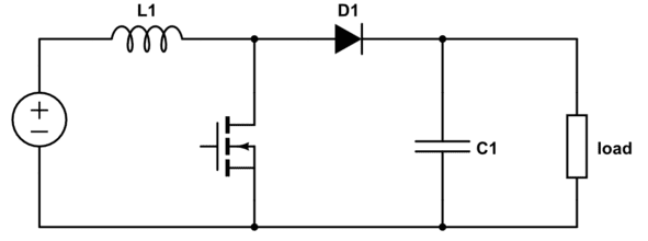
The maximum reverse voltage of 40 V is also important in a buck converter as it provides rectification during each switching cycle. Conversely, the low forward voltage is needed in a boost converter to pass power to the output of the circuit. The maximum reverse voltage value is much higher than the typical forward voltage value required to drive the 1N5822 to its maximum forward current, so for practical applications, you will only need to worry about the forward bias behavior.
The reverse bias behavior is more important for accidental bridging between the input and output sides of your regulator via the power rails, which creates a danger the diode fails if large voltage step-down functionality is needed in your switching regulator.
Switching Speed
A related requirement in the above application circuit is the switching speed. As the switching element modulates current flow through the inductor in the above circuit, the diode needs to respond and switch between forward and reverse bias suitably fast to prevent any power loss during switching.
However, the switching speed or edge rate will not be listed in a datasheet. Instead, the junction capacitance will typically be listed in the datasheet, which causes the transition between reverse and forward states to depend on any resistance in the voltage loop.
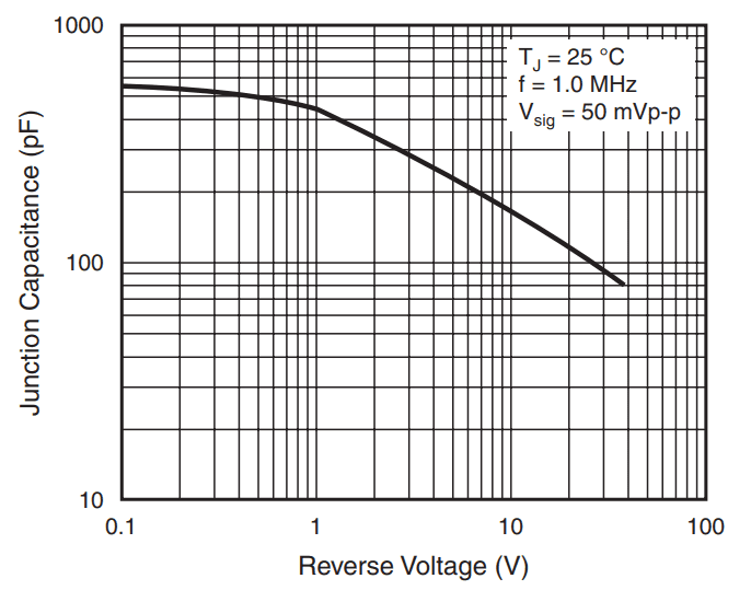
Example junction capacitance in reverse bias for the Vishay 1N5822-E3/54.
When you need to find a 1N5822 datasheet, footprints, and sourcing data, use the complete set of search features in Ultra Librarian. The Ultra Librarian platform gives you access to PCB footprints, technical data, and ECAD/MCAD models alongside sourcing information to help you stay ahead of supply chain volatility.
All ECAD data you’ll find on Ultra Librarian is compatible with popular ECAD applications and is verified by component manufacturers to help streamline your designing process.
Working with Ultra Librarian sets up your team for success to ensure streamlined and error-free design, production, and sourcing. Register today for free.


")