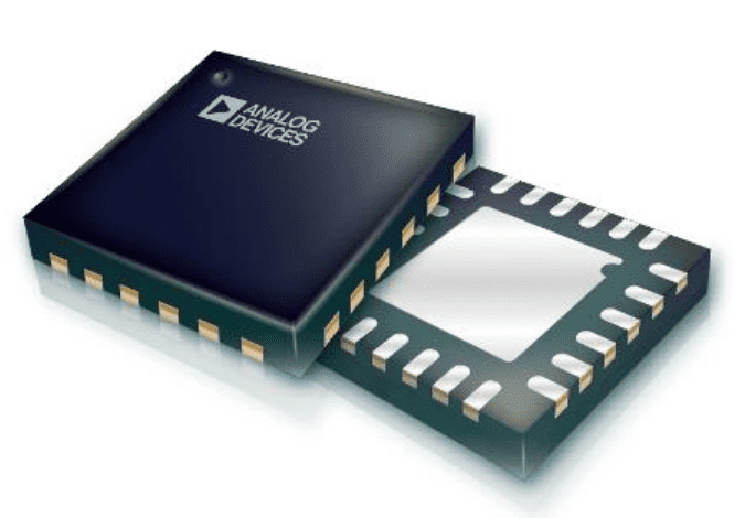
The AD7147 CapTouch™ programmable controller
(Source: Arrow)
The popularity of touch-based consumer electronics has exploded over the last few years. While touch-based devices are simple for the user, they involve complex processes for designers and engineers. The technologies that go into making these devices include such things as sensors and controllers to detect and interpret the motions of the user.
An excellent choice for many touch-based devices is the AD7147 CapTouch programmable controller by Analog Devices. This device is commonly used in consumer electronics, such as smartphones and gaming consoles, where the controller can be paired with sensors in buttons, scroll bars, and wheels. For PCB design, the AD7147 datasheet is an invaluable resource; however, it should be coupled with accurate CAD models for the most effective and efficient electronics development.
AD7147 Controller Applications
As described in the AD7147 datasheet, the controller is designed for portable systems that require high-resolution user input and supports the development of ultrathin consumer electronics for applications, as listed below.
Common AD7147 Applications
- Cell phones
- Personal music and multimedia players
- Smart handheld devices
- Television, audiovisual, and remote controls
- Gaming consoles
- Digital still cameras
As described in the AD7147 datasheet, the device is well-suited for use with single-electrode capacitance sensors. Additionally, the controller is designed to minimize interference at the input by employing an active shield.
The AD7147 utilizes external capacitance changes to initiate sensing activation. Developers and users can control operations by defining the setup of an integrated capacitance-to-digital converter (CDC) through internal register programming.
The device has two versions: the AD7147, with a serial peripheral interface (SPI)-compatible serial interface, and the AD7147-1, with an I2C-compatible serial interface. Both versions possess an interrupt output and a general-purpose input/output (GPIO), as well as a VDRIVE pin that sets the voltage level for the serial interface independent of VCC, according to the datasheet.
The AD7147’s operational units are shown in the functional block diagram below.
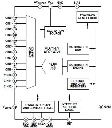
Functional block diagram of the AD7147 and AD7147-1 sensor controllers
Breaking Down the AD7147/AD7147-1 Pin Configurations
The pin configurations and function descriptions of AD7147 and AD7147-1 are shown below.
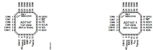
Note: The exposed pad is not connected internally. For increased reliability of the solder joints and maximum thermal capability, it is recommended that the pad be soldered to the ground plane.
AD7147 and AD7147-1 pin configurations
(Source: Analog Devices)
For more information about pin configurations and function descriptions, please refer to the AD7147 datasheet.
AD7147 Datasheet PCB Design Optimization
If you choose the wrong architecture or package type when designing with the AD7147 datasheet, you could end up redesigning, resending, and incurring additional development costs. Prevent these mistakes by sourcing schematic symbols, PCB layout footprints, and 3D CAD models from a reliable online component library, such as Ultra Librarian.
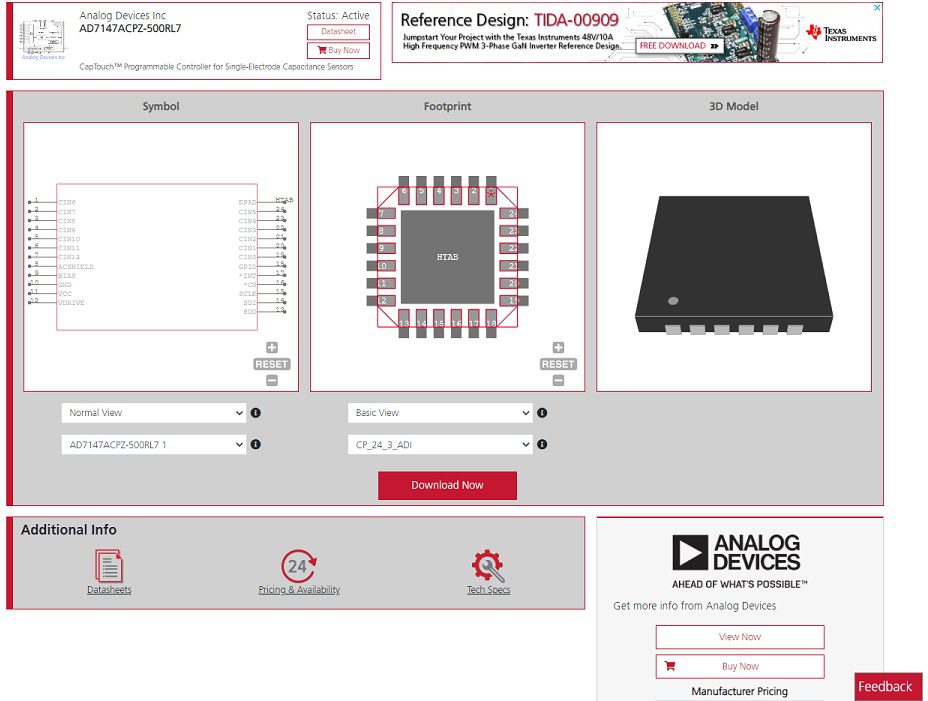
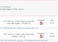
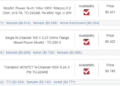
AD7147 symbol, footprint, and 3D CAD model
(Source: Ultra Librarian)
If you’re looking for CAD models for common components or important design information like the AD7147 datasheet, Ultra Librarian helps by compiling all your sourcing and CAD information in one place.
Working with Ultra Librarian sets up your team for success to ensure streamlined and error-free design, production, and sourcing. Register today for free.


")