The MSP430G2553 in 28-pin TSSOP
Extensive investigation or consideration is not necessary to understand what drives virtually all smart electronics product innovation. These technological advancements are possible due to the implementation of embedded systems. And the foundational elements of embedded systems are microcontrollers.
The MPS430 series of microcontrollers, produced by industry leader Texas Instruments Incorporated, provides engineers and developers with a series of microcontroller options for their embedded system applications. For medical device implementations, the MSP430G2553 datasheet is the best resource for understanding and leveraging the many features of this component for your design.
MSP430G2553: Specifications, Features, and Applications
The MSP430G2553 is a multi-mode low power microcontroller designed to aid in extended battery life operation for portable systems. The controller shares many specifications and features with other MSP430 series devices, which are summarized below.
The quantitative and qualitative attributes above make the MSP430G2553 an attractive microcontroller option for applications that require a cost-effective signal acquisition, processing and conversion solution for digital display or similar user interfaces (UIs).
MSP430G2553: Electrical and Thermal Parameters
The MSP430G2553 datasheet includes important parametric information; including maximum electrical and thermal ratings that are shown below.
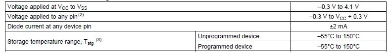
Absolute maximum ratings for the MSP430G2553 microcontroller
Operational recommendations for the controller are shown below.
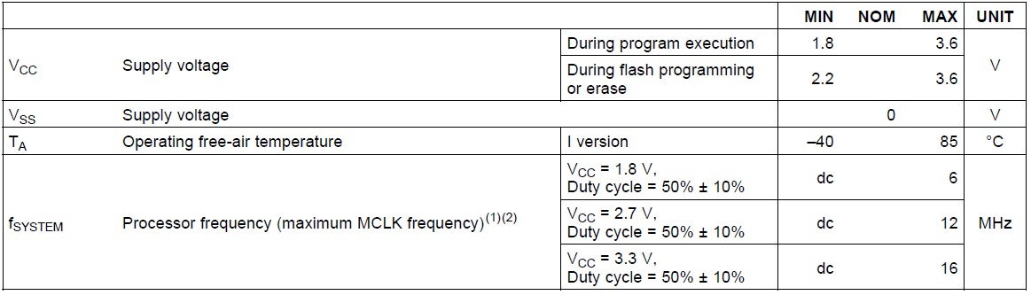
MSP430G2553 recommended operating conditions
Adhering to the recommendations above along with other parametric suggestions, such as the range of currents, will help ensure your device functions and operates reliably once deployed.
MSP430G2553: Layout and Operation
Functionality and operation of the MSP430G2553 are achieved with the layout shown below.
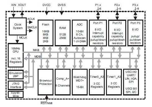
Functional diagram of the MSP430G2553 microcontroller
An important feature of the MSP430G2553 microcontroller is the six operation modes, which are listed in the table below.
As shown in the table, the device has five distinct low-power modes of operation. During low-power operation, the central processing unit (CPU) is disabled. Additionally, at least one clock is enabled for all modes, except Low-power Mode 4 when all clocks and the CPU are disabled. Available clocks include:
MSP430G2553 Clocks:
- ACLK Auxiliary clock (33 kHz watch crystal or internal low frequency oscillator)
- SMCLK Sub-main clock (used by peripheral devices)
- MCLK Main clock (used by CPU)
- DCO Digitally-controlled oscillator
- CO Controlled oscillator
As indicated, the controller has both fixed and multiple programmable clocks. Timing diagrams for various functions are given in the MSP430G2553 datasheet, along with other important information for your circuit board design.
PCB Design with the MSP430G2553 Datasheet
In addition to instructions–code and descriptions–and timing diagrams that are extremely important for flashing the MSP430G2553, which is done onboard, the device datasheet has essential data for component package selection and PCB layout. Available package options include 20-pin Thin Shrink Small Outline Package (TSSOP) and Plastic Dual Inline Package (PDIP), 28-pin TSSOP, and 32-pin Quad Flat Package (QFP). These are shown below.
Package Options
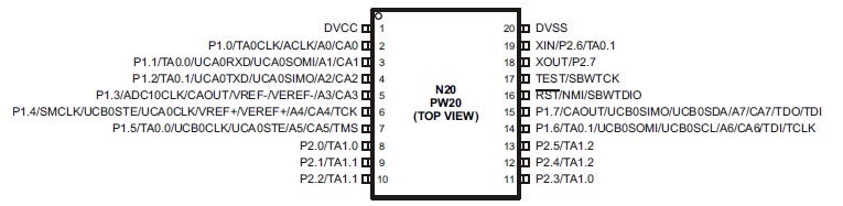
MSP430G2553 20-pin pinout
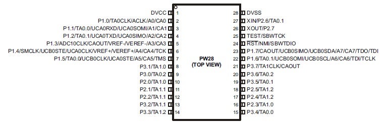
MSP430G2553 28-pin pinout
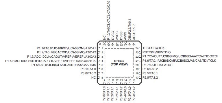
MSP430G2553 32-pin pinout
Information from the MSP430G2553 datasheet, as shown above, is critical for effectively utilizing the device in your design. It is also important to source data and CAD models for the microcontroller from a reliable component library resource. Following these guidelines will help you to most effectively develop your embedded system or other electronics product based around the MSP430G2553 controller.
If you’re looking for CAD models for common components or design information on how to best use the MSP430G2553 datasheet, Ultra Librarian helps by compiling all your sourcing and CAD information in one place.
Working with Ultra Librarian sets up your team for success to ensure streamlined and error-free design, production, and sourcing. Register today for free.