A single printed circuit board (PCB) failure in an aircraft flight controller or automated navigation system can end a mission and lives. That reality is why aerospace and defense PCBs are governed by performance specifications that commercial electronics never encounter. Navigating aerospace PCB Military Standard (MIL-STD) requirements demands close attention. Understanding which standards apply, when they apply, and what they actually require is the difference between hardware that passes qualification and hardware that gets rejected at the gate.
Why Commercial Standards Fall Short of Aerospace PCB MIL-STD Requirements
Aerospace PCBs operate under conditions that expose every design weakness. These boards must function reliably across a temperature range from -55°C to +125°C, withstand high-vibration profiles from engines and ordnance events, and operate in low-pressure conditions above 50,000 feet altitude. Standard commercial FR-4 and commercial manufacturing tolerances cannot meet these demands. Surviving extreme thermomechanical stress demands tight control over physical board features. Specifications like IPC Class 3 step in early to dictate strict baseline rules for annular rings, dielectric spacing, and copper plating integrity.
The substrate and laminate material choices for board fabrication reflect this gap:
- Polyimide substrates handle continuous high-temperature exposure without delaminating, making them the default for avionics and engine-adjacent applications.
- High-Tg FR-4 (glass transition temperature of 170°C or higher) provides a cost-effective alternative. It works well for environments that experience moderate heat loads rather than continuous extreme temperature exposure.”
- PTFE and Rogers laminates (such as Rogers 4003C) are required for radar and electronic warfare boards where signal integrity above 5 GHz is non-negotiable.
These designs require controlled impedance traces, careful grounding, and electromagnetic interference (EMI) shielding, while operating reliably across wide temperature ranges to maintain signal integrity. None of that is achievable without specifying the right standard from the start.
The Core Standards and What Each One Governs
| Requirement | Class 1: Consumer Electronics | Class 2: Dedicated Service Electronics | Class 3: High Reliability and Mission-Critical |
| Typical Use | Toys, remotes, and LED lights | Computers, tablets, and telecom | Aerospace, medical, and military |
| Internal Annular Ring | 0.0 mm (breakout OK) | 0.025 mm (1 mil) min | 0.05 mm (2 mil) min |
| Annular Ring Breakout | 180° allowed | 90° allowed | None permitted |
| Plated Hole Fill | Not specified | 75% (exceptions allowed) | 75% (no exceptions) |
| Copper Voids in Barrel | Acceptable | 5% of holes may have 1 void | Zero voids allowed |
| Inspection Requirements | Visual only | Visual + functional tests | Microscopic + stress testing |
| Relative Cost | $ | $$ | $$$ |
Aerospace PCB MIL-STD requirements and compliance do not fall into a single certification. It is a stack of specifications, each covering a distinct aspect of design, fabrication, or quality management. Relying on any one of them in isolation will leave gaps that auditors and qualification testing will find.
Applicable Standards & Quality Requirements for Military/Aerospace PCBs
| Standard | Primary Scope | Applies To |
| MIL-PRF-31032 | Performance and qualification rules for printed circuit boards and their constituent materials | All rigid, flexible, and rigid-flex military PCBs |
| MIL-PRF-50884 | Performance requirements for flex/rigid-flex (legacy programs) | Flexible and rigid-flex boards on legacy programs |
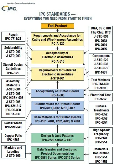
| IPC-6012 Class 3 / IPC-6012ES | Manufacturing acceptability of base materials, plating, and solder mask, alongside visual inspection of finished boards | Rigid boards; space and military avionics addendum |
| AS9100D | Aerospace quality management system | Facility qualification and supply chain control |
MIL-PRF-31032 constitutes performance and qualification requirements for rigid single-sided, double-sided, and multilayer printed wiring boards with or without plated through holes. Specifically, the standard sets strict limits on dielectric thickness and minimum peel strengths for copper traces. It caps allowable bow and twist limits. It also outlines exact tests for plating adhesion and baseline solderability. It replaced the older MIL-PRF-55110 standard and operates through a Qualified Manufacturers List (QML) program managed by the Defense Logistics Agency (DLA). Every PCB produced for the DoD must come from a facility on that QML list, and there are no exceptions.
MIL-PRF-50884 has been superseded by MIL-PRF-31032 as of December 31, 1997; however, legacy fabrication sites not certified to MIL-PRF-31032 can continue to certify to and build MIL-PRF-50884 part numbers. For new flexible and rigid-flex designs, the applicable slash sheets are MIL-PRF-31032/3 and /4. If your program references MIL-PRF-50884, confirm whether it is a legacy requirement before assuming the specification is still active for new qualification.
IPC-6012 includes addenda that impose requirements beyond standard Class 3, such as mandatory limits on plating voids, exact rules for dielectric separation, and tighter tolerances on microvia registration. The IPC-6012ES addendum should be specified for space, satellite, military aviation, and missile systems. For aerospace PCBs to meet these IPC Class 3 requirements, annular rings must meet minimums of 50 µm (0.002″) external and 25 µm (0.001″) internal, and through-hole copper plating must reach at least 25 µm (approximately 1 mil). Class 3 does not accept lifted or fractured annular rings — a defect that Class 2 tolerates under controlled conditions.
AS9100D builds on ISO 9001 with aerospace-specific mandates:
- Counterfeit part prevention requires strict vendor screening and material tracking to block fake components.
- Operational risk management demands failure modes and effects analysis (FMEA) to catch production bottlenecks early.
- Configuration control ensures you document every engineering change order (ECO).
You must then approve and track these changes across the entire supply chain. Unlike MIL-PRF-31032, which tests PCBs to certify they meet military performance needs, AS9100D focuses on the quality management system itself. Both are required.
Environmental Qualification Under MIL-STD-810H
MIL-STD-810H is the U.S. military standard that defines testing methods to evaluate the environmental durability and performance of equipment, simulating extreme conditions such as high and low temperatures, humidity, vibration, shock, sand, and dust. Its latest version was published in 2019, with a subsequent update (MIL-STD-810H Change Notice 1) released in 2022.
A critical point that trips up many programs: a common mistake in applying MIL-STD-810H is assuming that every test method applies universally. The standard promotes a tailoring process — identify the operational environments, then adjust parameters such as temperature ranges, vibration frequencies, and shock levels to match expected real-world conditions. You do not simply run every test method in the document. You build a test plan tied to the system’s specific life-cycle environmental profile. For instance, a flight controller inside a pressurized cabin undergoes different humidity and vibration tests than an exterior sensor array exposed to driving rain and heavy rotor resonance.
The most common test methods for aerospace PCB qualification cover three areas:
- Temperature shock (Method 503.7): Boards cycle between -55°C and +125°C to verify resistance to thermal expansion mismatch and prevent laminate delamination. Method 503 determines whether base laminates, copper bonding layers, and applied conformal coatings can withstand sudden changes in atmospheric temperature without physical damage or performance degradation.
- Vibration (Method 514.8): Tests evaluate board assemblies, solder joints, and heavy component mounts to verify their functionality and ability to withstand vibration exposure throughout their life cycle, including the synergistic effects of other environmental factors. Random vibration profiles for airborne electronics typically span 10 Hz to 2,000 Hz, with specific power spectral density levels defined per the platform.
- Mechanical shock (Method 516.8): Mechanical shock can adversely affect the physical and functional integrity of both the bare-board substrate and the populated component solder joints. Damage from mechanical shock is a function of the amplitude, velocity, and duration of the shock. Shock levels and pulse durations are tailored to the deployment platform — aircraft catapult events, weapons separation, and hard-landing loads all produce distinct shock profiles.
- Altitude and humidity (Methods 500.6 and 507.6): Low-pressure chamber testing simulates high-altitude operation, while humidity testing evaluates moisture ingress resistance. Specialized conformal coatings and low-moisture substrates are required to prevent conductive bridging and dielectric breakdown.
Documentation, Traceability, and Where Programs Fail
Strict documentation is not administrative overhead; it is how you prove the hardware is what you say it is. Documentation and traceability procedures for conformance inspection must match normal production procedures and include design, design rules, test procedures, and process rules. Under MIL-PRF-31032, Periodic Conformance Inspection (PCI) is typically done monthly, with data and results, including failure analysis, submitted to the qualification activity each month.
Traceability must extend from the Certificate of Compliance down to raw material certifications, including copper foil mill certs and laminate lot records. Holding an AS9100D certificate qualifies a supplier to enter the conversation. It hardly guarantees final hardware readiness, however. A facility might pass overarching quality audits but still lack the technical precision to hit the exact plating thicknesses or tight impedance limits demanded by flight-grade electronics. Engineers must look past the certificate. Audit a fabricator’s statistical process capability data directly.
Common Pitfalls in Aerospace PCB Compliance
The most common compliance failures in aerospace PCB programs:
- Insufficient copper plating in through-holes: IPC-6012 Class 3 sets a minimum of 25 µm (~1 mil) in through-hole barrels. Aerospace thermal cycling requirements frequently drive this to 38 µm (1.5 mil) or higher to prevent barrel cracking after repeated temperature excursions. Confirm your fabricator’s actual plated thickness data, not just their nominal process spec.
- Impedance tolerance gaps: High-speed signals often exceeding 5 GHz require precise impedance control (e.g., 50 ohms ±5%) to prevent data loss or interference. Many qualified fabricators can only hold ±10%. For radio frequency (RF) and microwave applications, verify high-speed PCB routing and controlled impedance capabilities before awarding the build.
- Traceability gaps: Undocumented engineering changes, missed First Article Inspection (FAI) steps, and incomplete lot records generate nonconformance findings. These do not just delay a program; they can trigger re-qualification. A forced re-qualification cycle halts hardware delivery entirely, burning through months of engineering schedule and multiplying project costs while the design undergoes testing from scratch.
- Supplier certificate over-reliance: A military PCB must meet IPC Class 3 requirements as a baseline, but MIL-SPEC certification adds additional testing, documentation, and process control requirements beyond IPC standards. Many manufacturers can produce IPC Class 3 boards, but MIL-SPEC certification requires DLA approval and ongoing compliance.
FAQ: Aerospace PCB Compliance
What is the difference between IPC Class 3 and MIL-PRF-31032?
IPC Class 3 defines acceptance criteria for high-reliability electronic assemblies. MIL-PRF-31032 adds government-specific requirements, including qualification testing, ongoing compliance verification, and DLA oversight. Class 3 is the manufacturing floor. MIL-PRF-31032 is the ceiling.
Is MIL-PRF-50884 still required for new flex PCB designs?
MIL-PRF-50884 is not for new designs. MIL-PRF-50884 is the corresponding performance specification for flexible and rigid-flex military PCBs, focusing on durability under bending and dynamic use, but new designs qualify under MIL-PRF-31032 slash sheets /3 and /4. MIL-PRF-50884 part numbers remain valid for legacy programs.
Is AS9100D certification mandatory?
For most defense prime contractors and their supply chains, yes, AS9100D certification is a standard contractual requirement. It covers counterfeit part prevention, configuration control, and risk management, as required by DoD programs.
Why does traceability matter beyond paperwork?
Traceability isolates failure modes in deployed systems and prevents counterfeit components from entering the supply chain. When a board fails in the field, lot-level traceability tells you exactly which other boards from the same production run may be at risk — and whether a fleet-wide action is needed.
How long does MIL-PRF-31032 qualification take?
The MIL-PRF-31032 qualification process typically takes 12 to 18 months from initial application to DLA approval, including establishing a Technical Review Board, developing a quality plan, producing qualification test vehicles, submitting samples for testing at DLA-certified laboratories, and passing an on-site audit.
Designing hardware that meets stringent aerospace PCB MIL-STD requirements is challenging, but sourcing the right components and optimizing thermal management shouldn’t be. Ultra Librarian streamlines your workflow by providing verified, highly accurate CAD models compatible with all popular ECAD applications. Accelerate your aerospace designs by instantly accessing schematic symbols, footprints, and 3D models from worldwide distributors, ensuring your supply chain is as reliable as your flight hardware.
Working with Ultra Librarian sets your team up for success, ensuring streamlined and error-free design, production, and sourcing. Register today for free.


 If you’re looking for any of our component footprints or models, we have readily available and free options for you and your design team. Search our library for the solution you’ve been looking for.