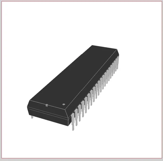
The PIC16F877A is an 8-bit microcontroller built on a Harvard reduced instruction set computing (RISC) architecture by Microchip Technology. Despite its age, it remains a fixture in embedded systems coursework, hobbyist prototyping, and legacy industrial hardware. You will often see it driving stepper motors in hobbyist robotics, managing sensor arrays in custom environmental data loggers, or functioning as the main logic controller in legacy industrial automation panels. As outlined in the PIC16F877A datasheet, the chip packs 200-nanosecond instruction execution, 35 single-word instructions, 256 bytes of EEPROM, two analog comparators, an 8-channel 10-bit analog-to-digital converter (ADC), two capture/compare/PWM (CCP) functions, and a synchronous serial port configurable as SPI or I2C into a 40-pin package.
Core Specifications from the PIC16F877A Datasheet
The chip operates over a voltage range of 2.0V to 5.5V, making it compatible with both 3.3V and 5V logic systems. Notably, most designs target 5V for compatibility with traditional peripherals like character LCDs and relay drivers. The operating speed runs from DC up to 20 MHz, yielding a 200 ns instruction cycle, with all single-cycle instructions except program branches, which take two cycles.
PIC16F877A Specification Summary
| Parameter | Specification |
| Operating Frequency | DC to 20 MHz (200 ns instruction cycle) |
| Operating Voltage | 2.0V to 5.5V |
| Flash Program Memory | 8K x 14-bit words (~14 KB) |
| RAM Data Memory | 368 bytes |
| EEPROM Data Memory | 256 bytes |
| Total I/O Pins | 33 across 5 ports (A, B, C, D, E) |
| ADC | 8-channel, 10-bit resolution |
| Serial Communications | SPI, I2C (via MSSP), USART |
| Timers | Two 8-bit (Timer0, Timer2), one 16-bit (Timer1) |
| Flash Endurance | 100,000 erase/write cycles (typical) |
| CCP Modules | 2 (Capture/Compare/PWM) |
The Flash program memory is rated at 100,000 erase/write cycles typical, and the chip supports single-supply 5V in-circuit serial programming (ICSP), a watchdog timer (WDT) with its own on-chip RC oscillator, programmable code protection, and a power-saving sleep mode.
Pinout and Built-in Peripherals
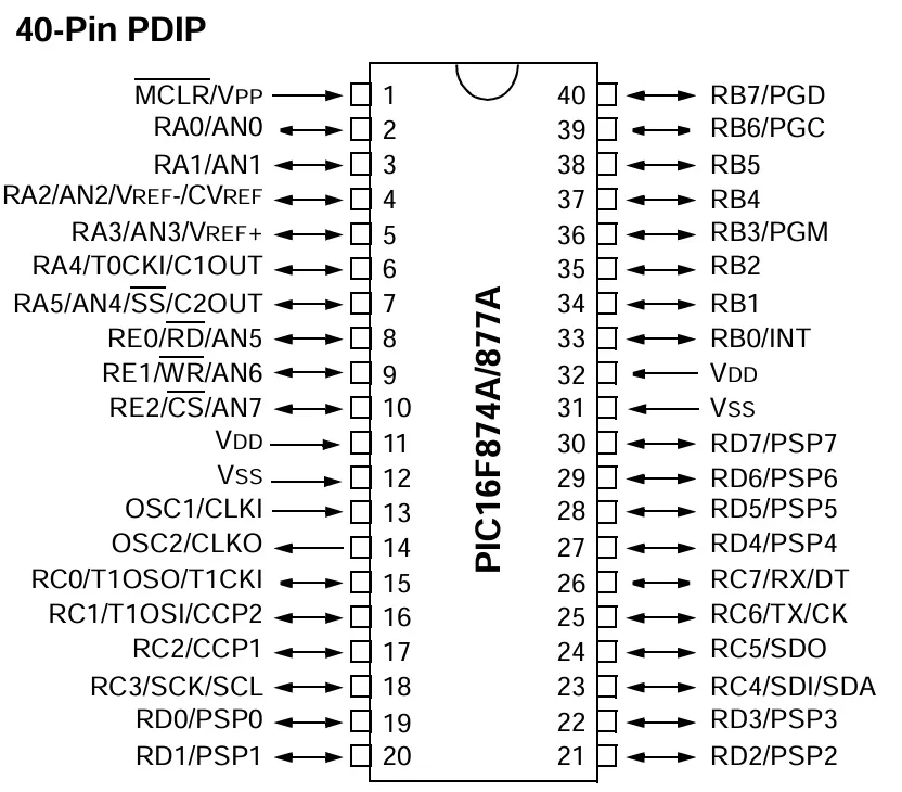
Microchip multiplexes the PIC16F877A’s I/O pins so that most serve multiple hardware functions depending on how you configure the control registers. The five ports: PORTA, PORTB, PORTC, PORTD, and PORTE–can function in both digital and analog modes, configured based on your specific requirements. In analog mode, the ports serve only as inputs through the built-in ADC and multiplexer circuits; in digital mode, you can configure each pin independently as an input or output through programming.
Here is how the ports divide functionally:
- PORTA and PORTE: Handle analog inputs. These pins route signals to the internal 8-channel 10-bit ADC or the two built-in analog comparators. Note that the comparators are enabled by default on power-up, which affects PORTA behavior — more on this in the FAQ below.
- PORTB: Dedicated to external hardware interrupts (pin RB0) and ICSP. Pins RB6 (PGC) and RB7 (PGD) serve as the programming clock and data lines.
- PORTC: Manages digital communications. It houses the master synchronous serial port (MSSP) pins for SPI and I2C, the USART module for serial RX/TX, and the CCP module outputs.
- PORTD: General-purpose digital I/O or a parallel slave port (PSP) for high-speed 8-bit parallel data transfers.
- PORTE: Three additional pins (RE0–RE2) that double as ADC inputs AN5–AN7.
The three timers, Timer0, Timer1, and Timer2, can operate in either timer or counter mode, and are used to generate PWM signals, delays, timer interrupts, and external event counts. Timer0 is an 8-bit timer that operates with an internal or external clock frequency; when used in timer mode, it runs on the internal frequency, and in counter mode, an external clock source triggers it. Timer1 is a 16-bit timer that operates in both modes, and Timer2 is an 8-bit timer used as a PWM time base for the CCP module.
How to Navigate the PIC16F877A Datasheet
The official Microchip datasheet (DS39582B) runs over 230 pages. You do not need to read it cover to cover; you treat it as a reference manual and jump directly to what your current task requires.
When starting a new project, go directly to the “Special Features of the CPU” chapter. This section contains the configuration word register. The bits inside this register are commonly called fuses. You must set these specific bits correctly to define your oscillator type, enable or disable the watchdog timer, and configure brown-out reset behavior. If your chip refuses to boot, the most likely cause is incorrect configuration bits, not your code.
Use these section shortcuts to pull critical data fast:
- Absolute Maximum Ratings (in “Electrical Characteristics”): Confirms the 5.5V VDD ceiling and per-pin current limits. The maximum current per port is 100 mA; an individual GPIO pin can safely sink or source approximately 25 mA. Do not drive more than a few LEDs directly from a single port without calculating the total port current — this is where engineers burn out I/O silently.
- I/O Ports chapter: Covers the TRIS and PORT register pair. Writing a 1 to a bit in TRISA sets that pin as an input, and writing a 0 sets it as an output. You configure ADCON1 here as well, which controls whether PORTA pins act as analog or digital I/O.
- Instruction Set Summary: Lists all 35 assembly instructions with syntax and status register effects. Useful even in C projects for understanding what the compiler is generating.
- Memory Organization: Explains the four-bank register file structure. The bank selects bits RP0 and RP1 in the STATUS register control, indicating which bank is active.
Hardware Implementation: What the Chip Needs to Run
The PIC16F877A does not boot from a power rail alone. You need a 2V-5.5V power supply, a crystal oscillator (up to 20 MHz), and two 22 pF capacitors to get the chip running. Follow the following hardware guidelines:
- Clock source: Connect a crystal oscillator across pins OSC1 and OSC2. Tie each pin to ground through a 22 pF load capacitor placed as close to the crystal as possible. Common choices are 4 MHz, 8 MHz, or 20 MHz crystals, depending on your timing requirements.
- Reset circuit: The MCLR pin is active-low. Connect a 10 kΩ pull-up resistor from MCLR to VDD to keep the chip running. Pull this pin to ground to trigger a hard reset. Do not leave MCLR floating.
- Power decoupling: Place a 0.1 µF ceramic decoupling capacitor directly across each VDD and VSS pin pair. Position the capacitor as close to the chip body as physically possible on the PCB. A decoupling cap on the other side of the board is nearly useless at filtering high-frequency switching noise.
- Comparator initialization: On power-up, the analog comparators on PORTA are enabled by default. If you need PORTA as digital I/O, write 0x07 to the CMCON register at the start of your code to disable them. Skipping this step is the most common reason code that worked on a PIC16F877 silently fails on a PIC16F877A.
Common Applications
The PIC16F877A is widely applied in remote sensors, security and safety devices, home automation, and industrial instruments. Its 5V logic makes direct interfacing with character LCDs, relay modules, and standard sensors straightforward. No level shifters are needed for the most common components. The 8-channel ADC is well-suited to reading multiple sensors simultaneously, and the two CCP modules handle PWM-based motor control without consuming CPU cycles.
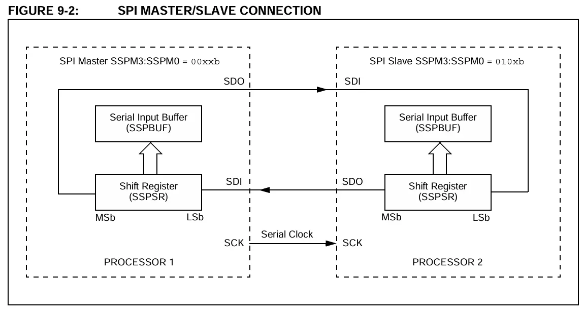
Microcontrollers like the PIC16F877A utilize serial interfaces like SPI to communicate with external peripherals.
Notably, however, the chip is less suited for applications requiring significant floating-point math, high-speed USB or Ethernet connectivity, or real-time operating system (RTOS) overhead. For those cases, the PIC18F or PIC32 families are more appropriate starting points.
Frequently Asked Questions
Does the PIC16F877A have an internal oscillator?
The PIC16F877A has an internal oscillator. Selectable oscillator options are listed in the datasheet, and the chip includes an internal RC oscillator. However, the internal oscillator’s accuracy is limited and temperature-sensitive. For any application requiring precise timing, USART communication, or tight PWM frequency control, use an external crystal. The watchdog timer also runs from its own independent on-chip RC oscillator, separate from the main clock.
Can the PIC16F877A be programmed in-circuit?
The PIC16F877A can be programmed in-circuit. ICSP is supported via two pins with single-supply 5V programming capability. You need five connections: MCLR (VPP), VDD, VSS, RB6 (clock), and RB7 (data). A PICkit 3 or PICkit 4 programmer handles this directly from Microchip’s MPLAB X integrated development environment (IDE).
What is the difference between the PIC16F877 and PIC16F877A?
The PIC16F877A is a newer part of the PIC16F877 with faster Flash programming (using a different programming algorithm) and adds a pair of analog comparators that are enabled by default (you must disable them via the CMCON register if you want the chip to behave like a 16F877). A hex file compiled for the 16F877 will generally run on the 16F877A, but the reverse is not guaranteed. The practical takeaway: always target the PIC16F877A in your toolchain configuration, explicitly disable the comparators in your initialization code, and do not assume a PIC16F877 programmer will work without updated firmware that supports the 877A’s different programming protocol.
Should I use the PIC16F877A for a new design?
You probably shouldn’t use the PIC16F877A for a new design, as it’s a legacy part. It is straightforward to swap from the PIC16F877A to the upgraded PIC16F887 with no changes to circuits or schematics; simply change the target device in MPLAB. The PIC16F887 offers the same 8K code space and 256 bytes of EEPROM while adding lower power modes, more ADC channels, and a calibrated internal oscillator. For new designs, the PIC16F877 is the better choice. The PIC16F877A remains relevant primarily for maintaining or understanding existing hardware.
Whether you are maintaining a legacy industrial system or prototyping a robust new digital circuit, understanding the PIC16F877A datasheet equips you with fundamental embedded hardware skills. Ready to bring your next microcontroller project to life? Ultra Librarian provides access to millions of verified CAD models, schematic symbols, and 3D footprints that integrate seamlessly into all popular ECAD applications, all sourced directly from reliable worldwide distributors to streamline your workflow.
Working with Ultra Librarian sets your team up for success, ensuring streamlined and error-free design, production, and sourcing. Register today for free.