Do you know what these PCB component codes mean?
Take a look at the top layer of any PCB or look in a datasheet, and you’ll find an alphabet soup of PCB component codes, markings on a PCB, abbreviations, and acronyms. It takes experience to keep it all straight, but it’s important for anyone in the industry to be able to quickly read PCB markings, component markings, and datasheet information. To help designers keep track of the wide range of PCB component codes, acronyms, and abbreviations, we’ve compiled a cheat sheet with essential information for designers.
Essential PCB Component Codes
When we refer to “PCB component codes,” we’re referring to a number of possible markings found on component packaging, an assembled PCB, or in datasheets:
- Reference designators: These codes are found on the surface layers of PCBs and are printed with silkscreen.
- Part numbers: This normally refers to the MPN on a component, but it could also be the part number printed directly on a PCB.
- Component markings: A component on a PCB could have some markings directly on the component, which may not be the MPN. Pinouts may also be printed on silkscreen near a connector.
- Component packages and footprints: While not printed on component bodies or on a PCB layout, the footprint information can be found in a component datasheet or manufacturer’s website.
- Digital protocols: A component datasheet may include multiple acronyms or codes that communicate specifications, digital signaling protocols, or other important data.
Reference Designators
Reference designators are very simple: they are printed directly on the surface layer of the PCB to denote specific components. Each component in a PCB is given its own reference designator, which is normally a letter and a number combination. Each reference designator in a PCB layout can be traced back to the bill of materials and schematics in your ECAD software. Here is a short list of reference designators on PCBs:
- U: Integrated circuits
- R: Resistors
- L: Inductors
- C: Capacitors
- J: Connectors
- T: Transformers
- TP: Test points
- P: Pads or pin headers
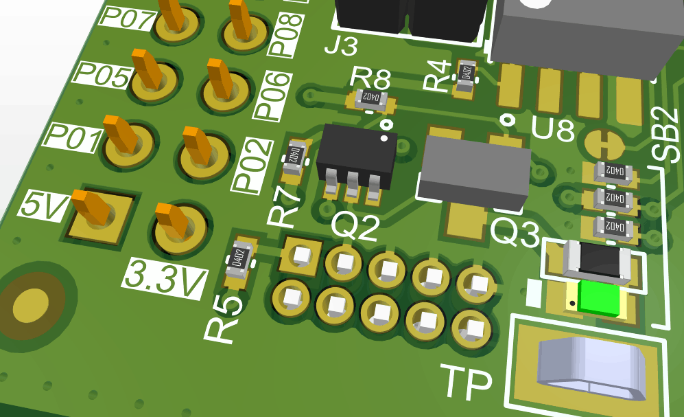
Example reference designators, pin names, and pin-1 indicators printed on the silkscreen layer in an assembled PCB
Component Markings and Part Numbers
Electronics companies will often print their part numbers on their PCBs to keep track of parts. Lot numbers and dates of production runs might also be printed on a PCB. These are printed on the silkscreen layer and provide a simple method for traceability to aid quality control. Part number formats are vendor-specific and product line-specific.
Components will have their own markings and part numbers. These are often the manufacturer’s part number (MPN), a name or brand for a specific product line, company logo, serial number, or some combination of these. This helps designers distinguish between different components in similar packages.
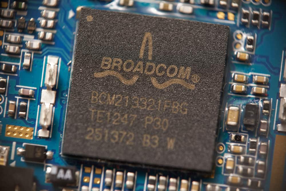
The BCM213321FBG from Broadcom includes multiple markings with serial numbers and other information from the manufacturer
Component Packages and Footprints
Datasheets will contain a package code for the component, which will generally match to a specific MPN. For components with IPC-standardized packages and dimensions, the package code will also specify the package dimensions and land pattern data. You could normally look up these specifications in the IPC-7351B standards (for SMT components) or the IPC-7251 standards (for through-hole components). However, datasheets will normally include a drawing showing the land pattern for the component that is used to create a PCB footprint.
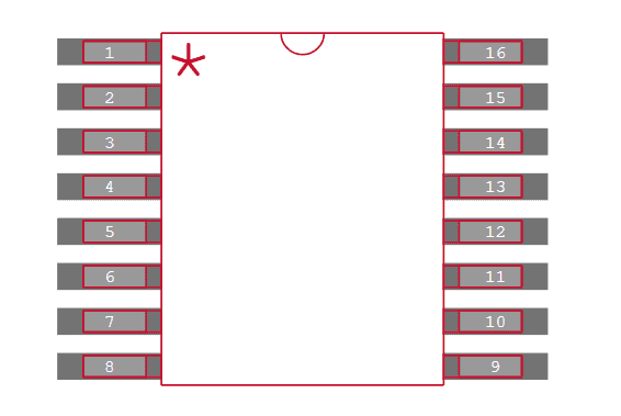
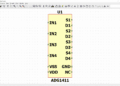
PCB footprint for the MAX1653EEE+T by Maxim Integrated.
Digital Protocols
Perhaps the most common component information found that will be written out as an acronym is signaling standards. There are a variety of low-speed and high-speed signaling standards that are used in various components. Some of the most common signaling standards used in many components are:
- I2C: Stands for inter-integrated circuit signaling, a bus protocol used by host controllers to exchange data with other integrated circuits.
- I2S: Inter-IC sound, a serial bus interface used to connect multiple digital audio devices together.
- SPI: Stands for serial peripheral interface, a synchronous serial communication interface used for full-duplex communication between a host controller and multiple peripherals.
- UART: Stands for Universal asynchronous receiver-transmitter, operates similar to SPI with configurable speed and data format.
- GPIO: Stands for general-purpose input/output, an uncommitted digital pin that can be configured by the user in the component’s firmware or with an external controller.
- USB: Universal serial bus, a high-speed differential interface that is used for many popular computer peripherals.
These are arguably the most popular digital interfaces used for communication between digital ICs. There are other low-speed and high-speed protocols that are more specialized, such as DDR and PCIe. Other component information may make reference to specific types of components, footprints, or other vendor-specific acronyms.
How to Find and Keep Track of Your Components
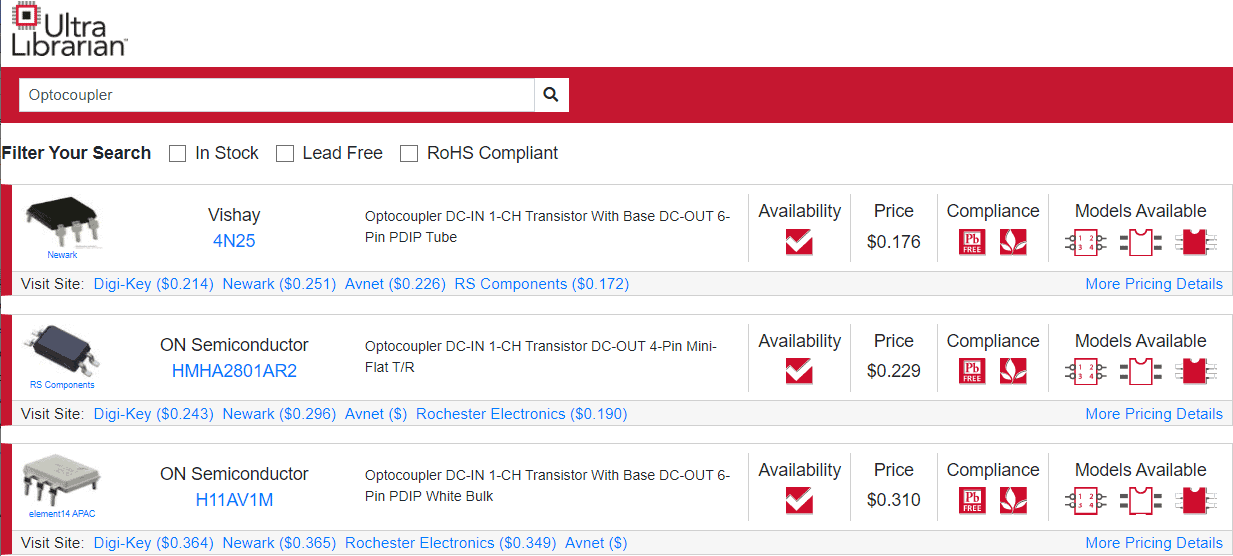
When looking for components for a new design, a designer will typically use MPNs, manufacturer names, product names, or electrical specifications. It’s also common to search by application and digital interface. No matter how you want to find your components, an electronics search engine can help you quickly find the parts you need.
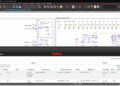
Example DC-DC converter reference design from Maxim Integrated
We hope this list of PCB component codes and acronyms will help you navigate the complex world of electronics and find the components you need. The next time you’re looking for components to put in a new design, try using the electronics search engine features in Ultra Librarian. When you use Ultra Librarian, you’ll have access to datasheets, technical specifications, CAD data, and verified 3D models that can be imported into popular ECAD applications.
Working with Ultra Librarian sets up your team for success to ensure streamlined and error-free design, production, and sourcing. Register today for free.