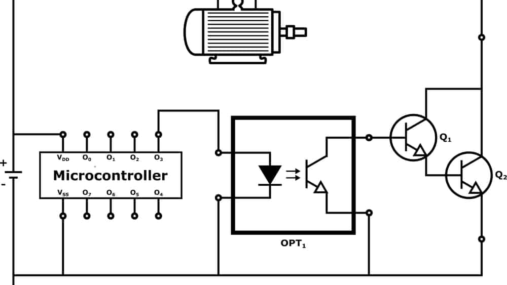
An example application of a photocoupler with Darlington connected phototransistors
Sometimes, a small variation or change can make a significant impact. Take, for example, the Darlington Raceway in South Carolina—deep in NASCAR country. Among some drivers and reverent fans, the track is referred to as “The track too tough to tame.” The racetrack was built in the late 1940s when top speeds for automobiles were just over 100 mph. However, due to an agreement to spare a minnow pond, the Darlington was built in an egg shape—one end sharper than the other and longer than other tracks. This seemingly small deviation resulted in the recognition that a higher level of performance could be achieved for stock car racing—significantly greater speeds.
Similarly, by making a small configuration change to BJT transistor circuits, a much higher performance can be achieved—significantly greater gains. BJTs have long been used as amplifiers in countless electronic circuits. This is due to their relatively high current gain—collector current to base current—potential of 50 to 200. However, there are times when even higher gain is desired or needed. One way to achieve higher output current without increasing the input current is to connect two transistors in a Darlington configuration. Many components take advantage of this arrangement. In this article, we take a closer look at the TLP627 datasheet, which provides details and specifications that are important for understanding how to take advantage of this configuration.
Understanding the Darlington Configuration
If you work with transistor circuits often then you know that you can multiply the voltage gain by adding amplifier stages. For example, if the voltage gain of a single BJT common emitter amplifier is Av1, then by connecting the output—from the collector—to the input—base—of a second identical transistor, an overall voltage gain of approximately Av = Av1 x Av2 can be achieved.
The gain in current when using a Darlington configuration, as shown in the figure below, is similar.
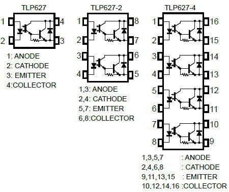
TLP627 package options
The images above, from the TLP627 datasheet, illustrate the Darlington configuration or pair utilized in the popular component from Toshiba. Let’s assume a pair of identical amplifiers—the gain is determined by beginning with the basic current gain equation for the pair.
| Darlington current gain, ΒD = Ie2/Ib1 | (1) |
| Now, substituting for Ie2 | |
|
ΒD = (Ib2 + Ic2)/Ib1 |
(2) |
| Recalling the current gain of a single transistor is Ic = ΒIb and substituting for Ic1 in Eq. (2), gives | |
|
ΒD = (Ib2 + Ib2Β)/Ib1= Ib2(Β + 1)/Ib1 |
(3) |
| Since, Ib2=Ie1, Eq. (3) becomes | |
|
ΒD = Ie1(Β + 1)/Ib1 |
(4) |
| Now, substituting for Ie1 | |
|
ΒD = Ib1(Β + 1)(Β + 1)/Ib1=(Β + 1)(Β + 1) |
(5) |
| Multiplying the factors yields | |
|
ΒD = Β2 + 2Β + 1 |
(6) |
| In general form for any two amplifiers, Eq. (6) becomes | |
|
ΒD = Β1Β2 + Β1 + Β2 + 1 |
(7) |
| Finally, noting that Β1Β2 >> (Β1 + Β2 + 1) | |
|
ΒD = Β1Β2 |
(8) |
For further amplification, additional transistors can be added to the Darlington configuration as required.
The TLP627 Applications, Parameters, and Alternatives
Darlington pairs are relatively simple circuit designs. The TLP627, which this configuration is utilized within, is a bit more complex. To complete the component package, infrared (IR) photocoupling is added, which is directly applied to the Darlington pair input. Additionally, a base-emitter resistor to improve switching and aid thermal characteristics is included. These devices are routinely used in telecommunications systems and as programmable DC controllers for various loads, such as motors.
In the table below, the max ratings for the TLP627 are given.
Absolute Maximum Ratings |
|||
| Characteristics | Symbol | Rating | Unit |
| Collector-emitter voltage | VCEO | 300 | V |
| Collector current | IC | 0.15 | A |
| Operating temperature | Topr | -55 to 100 | ℃ |
As shown above, the device has a relatively high output voltage, which makes it usable for a wide range of load system operations. The electrical characteristics are shown below.
Electrical Characteristics |
||||
| Characteristics | Symbol | Condition | Value | Unit |
| Collector-emitter saturation voltage (Max) | VCE(sat) | IC=0.1A
IF=10mA |
1.2 | V |
| Isolation voltage BVs
@1minute (Min) |
BVS | t=60sec | 5000 | Vrms |
| Current transfer ratio (Min) | CTR | IF=1mA
VCE=1V |
1000 | % |
The TLP627 is a reliable component that has been utilized in many designs and products. However, as indicated in the TLP627 datasheet, the manufacturer recommends using the TLP627M—which comes in the same package but may provide better overall performance, especially noise suppression—or the TLP387, which comes in a longer, flatter surface mount 4-pin SO6L package.
How to Best Use the TLP627 Datasheet for PCBA Design
The TLP627 datasheet is a great resource for understanding the operation of the component. It is also very useful when it is necessary to create symbols and landing patterns from scratch. However, it is highly recommended that an online library, where CAD data and imagery (as shown below) is easily accessible, be used instead.
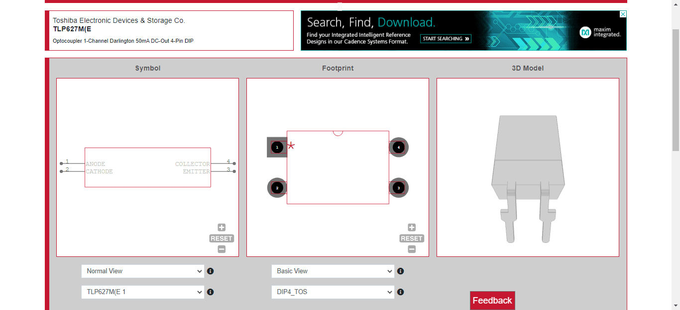
CAD images for TLP627(M) from Ultra Librarian
Not only is CAD data, which is preferred by most CMs, easily available, but you can avoid component availability problems and the pitfalls of manual footprint creation. If you’re looking for CAD models for common components or recommended alternatives as suggested by the TLP627 datasheet, Ultra Librarian helps by compiling all your sourcing and CAD information in one place.
Working with Ultra Librarian sets up your team for success to ensure streamlined and error-free design, production, and sourcing. Register today for free.