
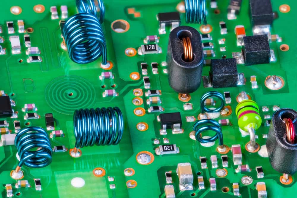
PCB with surface mount and through hole components
Paper or plastic packaging? Red or white wine? Michael or LeBron? Tabletop or video games? These are just a few of the perplexing questions in life that many people struggle with. As PCB designers, we have our own bewildering issue. Surface mount components or through hole.
Although, surface mount parts have been around since the 1960s, through hole components dominated the market until the 1990s. Today, most components are available in surface mount technology SMT) packaging , especially integrated circuits. This prevalence, coupled with the distinct advantages of opting for each type, make it imperative that engineers and PCB designers know when and how to choose between surface mount components vs through hole.
Comparison: Surface Mount Components vs Through Hole
As the demand for smaller electronics continues to grow, the utilization of surface mount components instead of through hole components increases. Smaller and lighter components is a one of the major assets that surface mount components bring to a design. However, there are benefits unique to through hole parts, as well. The advantages of both component types are listed below.
It is obvious from the table above that comparing surface mount components vs through hole is not a simple apples to apples evaluation. In fact, each component type has some distinct benefits that make it the logical, if not only, option for some situations. Therefore, the question is not which is better than the other, but when is the best time to choose which component type?
Surface Mount or Through Hole? How to Choose
Part selections are the most important decisions that designers make during the PCBA design process. Typically, the component datasheet is the primary source of determinant qualitative and quantitative information, such as common applications and electrical characteristics, respectively. Yet, the fact that your component choices impact all three aspects of the design⇒build⇒test (DBT) process, necessitate that design for manufacturing (DFM), design for assembly (DFA), and design for testing (DFT)–if necessary–are considered.
For guidance In choosing whether to use surface mount components vs through hole that best satisfies your circuit’s functionality and performance objectives, while also adhering to manufacturing requirements it is helpful to answer the following questions.
The questions above will help you choose between surface mount technology (SMT) and through hole technology (THT) as a component selection strategy. The chief advantages of opting for a broad strategy is that it simplifies the assembly process for your CM, as surface mount components and through hole components typically involve different soldering processes. For SMT, reflow is the standard soldering method. For THT, wave soldering is most often implemented.
In some cases, for example when parts are not available in one of the surface mount device (SMD) packages, both SMT and THT must be utilized. Therefore, it is necessary to choose between surface mount components vs through hole for individual parts. Doing so will enable you to optimize your design for the most efficient PCB development process.
Optimizing Your SMT and/or THT PCB Design
Choosing the wrong components is one of the most costly errors you can make with your design. Replacing components almost always leads to the need for redesign, respin and retesting. Therefore, it is imperative to optimize your component selection the first time, for an efficient and cost-effective development process. Accomplishing this is best achieved by following guidelines, as listed below.
 Understand the benefits and advantages of choosing
 If you’re looking for CAD models for common components or important design information about surface mount components vs through-hole, Ultra Librarian helps by compiling all your sourcing and CAD information in one place.
Working with Ultra Librarian sets up your team for success to ensure streamlined and error-free design, production, and sourcing. Register today for free.


