Sometimes, terminology in the electronics industry gets a bit chaotic, which filters down to actual products you can purchase from component manufacturers. A great example is the differences between evaluation boards vs. development boards. As a result, many manufacturers release products they explicitly label as “evaluation kits” or “evaluation boards” as well as a different set of products labeled “development kits” or “development boards.”
These products are PCBAs that feature a specific component. The board is designed to access interfaces for configuration, flashing, and connecting to other hardware. These designs are very similar, and the differences between an evaluation board vs. development board can be difficult to see if you’ve never used these products. In this article, we’ll explore these differences and whether they actually matter for your development process.
Understanding Evaluation Boards vs. Development Boards
These two terms can be confusing because some manufacturers use each term to mean different things. Typically, either of the two terms could refer to a finished PCBA with the following characteristics:
- The design is built around a specific component, giving the designer the ability to experiment with the component on an assembled board that is known to work properly.
- All digital and analog interfaces are exposed at connectors and/or test points so that peripherals and other evaluation/development boards can be connected.
- Other supporting circuitry required for basic functions, such as power regulation or antenna routing, are implemented on the board and do not need to be added externally.
- For programmable components (MCUs, etc.), the board will have a flashing interface exposed through a connector, usually a pin header or USB connector.
- These products go through extensive testing to ensure they function as intended and that all functions on the main component are accessible.
The problem with these terms is that some manufacturers intend their use for different stages of design and development, which gets reflected in the design of the evaluation/development board.
Evaluation Boards
Some component manufacturers will produce an evaluation board so a component can be evaluated in a particular application. For example, consider the LM3464EVAL from Texas Instruments; this evaluation product is a 4-channel LED driver board. It can interface with a power converter module or other systems as part of proof-of-concept design and prototyping. The use of these boards allows a designer to evaluate the capabilities of a new product before adding it to a new design.
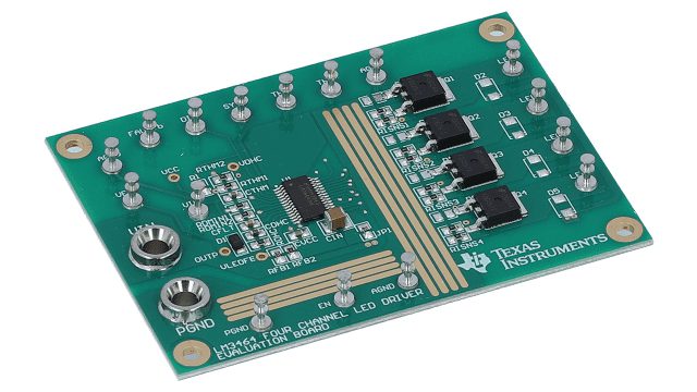
LED driver evaluation board (LM3464EVAL) from Texas Instruments [Image source: ti.com]
Development Boards
The name “development board” implies that you can use the board to develop an application; thus, this term often refers to boards used with programmable ICs. Firmware developers often use development boards to test their code in isolation, followed by testing with other peripherals.
When multiple ICs need to work together to create a desired functionality, multiple development boards can be connected so that the firmware can be tested and debugged before being flashed onto a prototype. Although these boards imply their use is in application development, they can be used for general testing of any other hardware that might connect to your system, so it can be challenging to see how these boards are different.
Evaluation Boards vs. Development Boards: Are They Different?
The answer is: sometimes. Some companies will market an evaluation board and a development board for the same product, but both boards’ functions will overlap. This similarity makes it impossible to really see how these products are different.
For example, take a look at the 5P49V6965 from Renesas. There is a development board (called a “programming kit” under MPN: 5P49V6965-PROG) and an evaluation board (5P49V6965-EVK) for this component. If you read the datasheets for these boards, you’ll find that both products are intended for application development on a PC. The main difference appears to be that the 5P49V6965-PROG does not expose some interfaces exposed on the 5P49V6965-EVK, which is the reverse of what you would expect from an application development perspective.
To make things less clear, some manufacturers make no distinction between these products. In fact, Maxim Integrated notes that the terms “evaluation kit” and “development kit” are synonymous in their glossary:
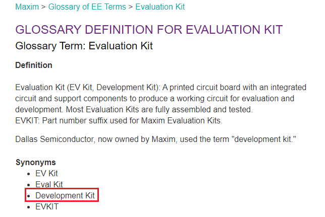
Whether you call it an evaluation kit or development kit, these products are handy for application developers and hardware designers. They allow the designer to focus on designing connectivity and functionality before making a large purchase, rather than focusing on the finer points of PCB layout for a component that might never be used. Another tool designers often use is reference designs, which might be selected after thorough testing with an evaluation board or development board.
What About Reference Designs?
There are also reference designs to consider when distinguishing evaluation boards vs. development boards. A reference design is very different from an evaluation or development board, although it might share some of the same components and design characteristics. Even worse, some manufacturers also refer to their reference designs as evaluation boards!
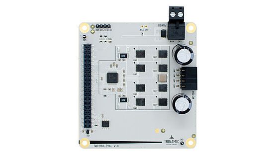
Example reference design from Trinamic (TMC2160-EVAL). Trinamic calls this particular reference design an “evaluation kit.”
A reference design is meant to be an example product centered around a specific component. The point of a reference design is to illustrate how a component can be implemented in a real product and how that component is connected to other important components or circuits needed to make the example product work properly. Reference designs are intended to be reverse-engineered and adapted into similar products. Sometimes, large blocks are taken from reference design schematics and copied directly into a new product.
Some reference designs can be used similarly as a development board, particularly when they require some programming. Designers can still use these types of boards for application development as well as hardware development. One factor distinguishing reference designs is that these designs are not always centered around one component, in contrast to a development board or evaluation board. For example, take a look at the MAXREFDES103. This design is built around two primary components: the MAX32664 and MAX86141. This type of pairing is typically not seen in evaluation boards or development boards.
Where to Find Evaluation Boards and Development Boards
The best way to find and compare evaluation boards vs. development boards is to use a comprehensive electronics search engine. Ultra Librarian’s parts database includes evaluation kits, development kits, and variants for many part numbers, technical documentation and datasheets, and sourcing data for these products. Once you’ve built and tested your application with these products, you can also use Ultra Librarian to find additional components (including symbols and footprints) for your design. Once you’ve found a component you like, you can look on the manufacturers page to find interactive reference designs for your components.
The electronics search engine features in Ultra Librarian do more than help you find new parts and sourcing data. The platform gives you access to PCB footprints, technical data, and ECAD/MCAD models alongside sourcing information to help you stay ahead of supply chain volatility. All ECAD data you’ll find on Ultra Librarian is compatible with popular ECAD applications and is verified by component manufacturers.
Working with Ultra Librarian sets up your team for success to ensure streamlined and error-free design, production, and sourcing. Register today for free.