The LM2596 is notorious in discrete power supply design, and for good reason: it delivers a regulated 3A output with only four external components. If you’re designing a step-down power stage and want a proven, well-documented IC with broad manufacturer support, this is where to start.
The LM2596 datasheet states that these integrated circuits provide all the active functions for a step-down (buck) switching regulator, capable of driving a 3A load with excellent line and load regulation. Fixed-output-voltage versions are available at 3.3V, 5V, and 12V, plus an adjustable-output version. Internal frequency compensation and a fixed-frequency oscillator minimize the number of required external components.
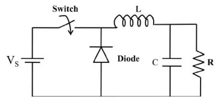
How the LM2596 Step-Down Regulator Works
Because the LM2596 is a switch-mode power supply, its efficiency is significantly higher than that of popular three-terminal linear regulators, especially at higher input voltages. The LM2596 operates at a fixed switching frequency of 150 kHz, allowing smaller filter components than would be needed with lower-frequency switching regulators. That 150 kHz figure matters practically: it’s why the LM2596’s inductors and capacitors are physically smaller than those used in the older LM2576, which uses an internal fixed-frequency oscillator running at 52 kHz.
Output voltage tolerance is ±4% under specified input voltage and load conditions, with ±15% on the oscillator frequency. External shutdown is included, with a typical standby current of 80 µA. Self-protection features include a two-stage frequency-reducing current limit for the output switch and an overtemperature shutdown for complete protection under fault conditions.
LM2596 Pinout and Package Options
The LM2596 is available in a standard 5-pin TO-220 package with several lead-bend options, as well as a 5-pin TO-263 surface-mount package. Getting the physical layout right matters as much as the schematic. Switching currents are large and fast, so trace routing directly affects noise and efficiency.
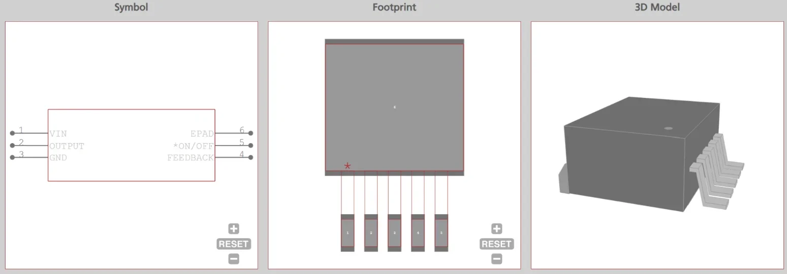
Each pin has a specific function that drives layout decisions:
- Pin 1 (VIN): Positive input supply for the IC switching regulator. A suitable input bypass capacitor must be present at this pin to minimize voltage transients and supply the switching currents needed by the regulator.
- Pin 2 (OUTPUT): The emitter of the internal switch. The saturation voltage (VSAT) of this output switch is typically 1.5V. The PCB area connected to this pin should be kept to a minimum to reduce coupling to sensitive circuitry.
- Pin 3 (GROUND): Circuit ground reference.
- Pin 4 (FEEDBACK): Senses the regulated output voltage to close the internal control loop.
- Pin 5 (ON/OFF): Allows the switching regulator to be shut down using logic-level signals, dropping total input supply current to approximately 80 µA. The threshold voltage is typically 1.6V.
Key Electrical Specifications from the LM2596 Datasheet
The adjustable output voltage range spans 1.23V to 37V, with a guaranteed 3.0A output load current and a wide input voltage range up to 40V.
LM2596 Electrical Characteristics
| Parameter | Min | Typical | Max |
| Input Voltage Range | 4.5V | — | 40V |
| Output Current | — | — | 3.0A |
| Adjustable Output Voltage | 1.23V | — | 37V |
| Switching Frequency | 127 kHz | 150 kHz | 173 kHz |
| Quiescent Current | 5.0 mA | 10 mA | |
| Standby Quiescent Current | — | 80 µA | 200 µA |
| Output Voltage Tolerance | — | — | ±4% |
Note that the ±15% oscillator frequency tolerance means you must select inductors and capacitors with enough margin to handle switching frequency variation across the full production spread.
External Component Selection
Designing with the LM2596 requires four external components. Choosing them correctly determines whether your supply runs reliably or trips protection at the worst possible moment.
- Input Bypass Capacitor: Requires low equivalent series resistance (ESR) to handle transient currents and prevent input voltage sag. For an aluminum electrolytic, the capacitor voltage rating should be approximately 1.5 times the maximum input voltage. A 680 µF/35V capacitor is a common choice for designs up to 35V input.
- Catch Diode: A Schottky diode is mandatory. The catch diode current rating must be at least 1.2 times greater than the maximum load current. For a design that must withstand a continuous output short, the diode should be rated equal to the LM2596’s maximum current limit. Standard 50/60 Hz rectifier diodes will cause excessive power dissipation and erratic behavior.
- Inductor: Must be rated for peak switch current to prevent core saturation. A standard series of inductors from several different manufacturers is optimized for use with the LM2596 series.
- Output Capacitor: Output ripple voltage is a function of the inductor sawtooth ripple current and the ESR of the output capacitor. Typical output ripple ranges from approximately 0.5% to 3% of the output voltage. To obtain low ripple, the ESR must be low; however, extremely low ESR capacitors can affect loop stability and cause oscillation.
The LM2596 datasheet provides graphs and formulas for inductor selection, keyed to your specific input voltage, output voltage, and maximum load current. Use them. Guessing on inductor value is a reliable path to discontinuous-mode instability or saturation.
Thermal Management: The Real Limit at 3A
The 3A rating is not a free pass. Heat dissipation is the binding constraint in most real-world LM2596 designs, and it’s where cheap modules consistently fall short.
Although the TO-220 package requires a heatsink under most conditions, some applications can operate without one to keep the LM2596 junction temperature within the allowed operating range. Higher ambient temperatures require some heat sinking, either to the PCB or an external heatsink.
Key thermal management design rules by package:
- TO-220: Requires an external heatsink for continuous loads above approximately 1.5A. Without one, junction temperature climbs rapidly toward thermal shutdown.
- TO-263 (surface-mount): Relies entirely on PCB copper area for cooling. The optimal thermal configuration uses a double-sided PCB with 3 in² of copper on the LM2596S side and approximately 16 in² of copper on the other side.
- Pre-built modules: Inexpensive commercial buck modules often trigger thermal shutdown below 1.5A. These modules typically lack adequate heatsinking for both the main IC and the catch diode.
When an output short or overload causes the regulated output voltage to drop approximately 40% from its nominal value, the oscillator frequency reduces to approximately 30 kHz. This self-protection feature lowers average IC dissipation by reducing the minimum duty cycle from 5% down to approximately 2%. Thermal shutdown adds a second layer of protection when that frequency reduction isn’t enough.
Common Application Questions
What is the difference between the LM2576 and LM2596?
The LM2576 oscillator frequency is 52 kHz. The LM2596 runs at 150 kHz. That nearly 3x frequency difference allows the LM2596 to use physically smaller inductors and capacitors, reducing PCB footprint and bill-of-materials cost.
Can the LM2596 output 3A without a heatsink?
No, the LM2596 can not output 3A without a heatsink. Running 3A continuously without a heatsink will push the junction temperature toward the thermal shutdown threshold. The practical continuous limit without additional cooling is closer to 1.5A, depending on the input-to-output voltage differential and ambient temperature.
What happens if the input voltage drops below the output voltage?
The LM2596 is exclusively a buck (step-down) converter, so if the input drops below the setpoint, the output will track below the input. The internal switch has a typical VSAT of 1.5V, so the output will sit roughly that far below the input rail under those conditions.
What are typical LM2596 applications?
The LM2596 is used for adjustable, step-down circuits across many applications, including battery chargers and embedded regulator modules. Automotive power equipment is another strong fit, since input voltages can fluctuate significantly while the load demands stable regulation.
Ready to build your next power supply circuit? Turning insights from the LM2596 datasheet into a reliable PCB layout starts with accurate CAD models. Ultra Librarian delivers verified footprints, symbols, and 3D models directly into popular ECAD applications, helping you source components quickly from worldwide distributors. Stop redrawing footprints and start designing with confidence.
Working with Ultra Librarian sets your team up for success, ensuring streamlined and error-free design, production, and sourcing. Register today for free.


")