
Instrumentation amplifiers are used to provide high precision measurement and signal reproduction with variable gain
Amplifiers are fundamental analog circuits meant for signal reproduction and magnification, and they are an important part of analog and mixed-signal systems. There are a variety of amplifier ICs available for different applications, with some of the primary selection criteria being DC gain, bandwidth, and classification. If you need accurate signal collection and reproduction with variable gain, one option is to use an instrumentation amplifier (in-amp).
One low-cost, high-precision in-amp is the AD620 from Analog Devices. This simple component enjoys multiple precision measurement applications in medical instruments, DAQ cards, transducers, and industrial automation. If you’re interested in this type of component, let’s look at the AD620 datasheet and see how it stacks up to other types of amplifiers.
Instrumentation Amplifiers (In-Amps)
All in-amps are differential amplifiers that can be used to measure low-level signals in a noisy environment. These amplifiers can be implemented with or without an external feedback network, depending on the topology of the amplifier. The advantage of an instrumentation amplifier is that the gain can be easily set using an external precision resistor and by adjusting a DC offset on the differential input. In this way, the output can be switched between inverting and non-inverting by applying some DC offset or switching the polarity of the inputs.
The image below shows a typical circuit diagram and gain equation for an instrumentation amplifier. In this topology, three op-amps are used with their inverting terminals bridged using a resistor. The inputs are normally configured such that V2 is high to give a non-inverting output. The amplifier can also be configured so that V1 is grounded while V2 is the signal to be amplified.
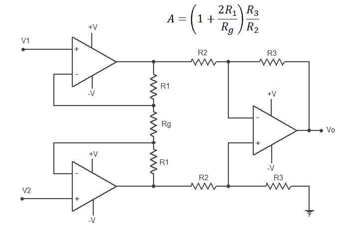
Instrumentation amplifier circuit diagram
Selecting Gain
The output gain from the above circuit is set entirely with the gain resistor Rg. The other resistors in the circuit are internal to the component and cannot be selected by the designer. Feedback can be applied back to the HIGH input in the above equation, but this is not required and will change the total gain of the component, basically creating a composite amplifier. Finally, the gain resistor can be omitted, meaning the circuit would have infinite Rg.
Drawbacks of Instrumentation Amplifiers
The main drawback of this type of amplifier is the inability to select the internal components. Theoretically, infinite gain will be seen when Rg = 0, but in reality, the gain will saturate from 10,000 to 100,000 for these types of amplifiers. In addition, reactive components (for example, a capacitor in a feedback loop) can’t be added to provide filtering because everything is integrated into the package.
If you want greater control over the operating characteristics of this type of amplifier, you can construct the above circuit from discrete op-amps and resistors. There are quad op-amp components available that can be used to easily layout a custom instrumentation amplifier. Metal-film resistors are usually the best components to use for the feedback and gain resistors, as they provide high precision with high power dissipation.
The AD620 Instrumentation Amplifier
A low-cost, high-precision instrumentation amplifier option is the AD620 from Analog Devices. This simple DIP-8 component provides low-noise signal amplification, high CMRR, and a maximum gain of 10,000. The diagram below shows the AD620 pinout with connected gain resistor.
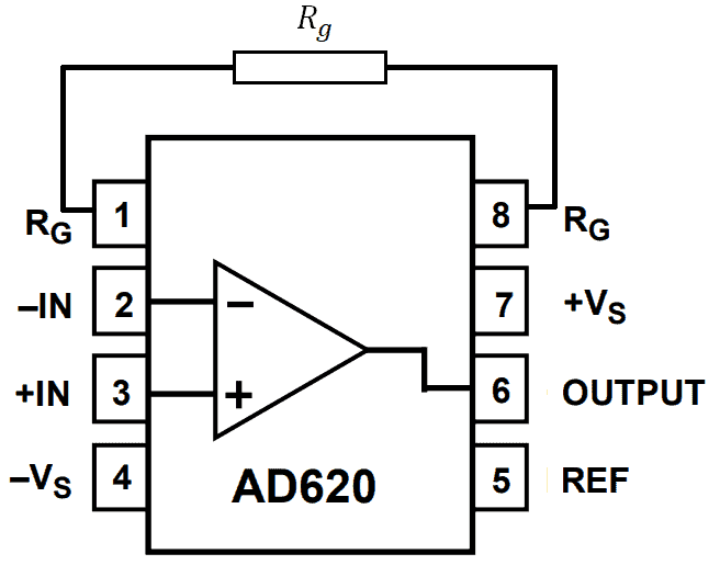
The AD620 pinout from the AD620 datasheet
This in-amp can be used for a range of applications and frequencies, thanks to its large gain-bandwidth product. In addition, this component is an excellent choice for environments with the potential for high noise, such as in an industrial environment or in mixed-signal systems.
What’s in the AD620 Datasheet?
The AD620 datasheet contains a wealth of information needed to implement this component in an instrumentation system as well as technical specifications. The table below shows the basic specifications of the AD620.
| Max. Supply Voltage | +/- 18 V |
| Slew rate | 1.2 mV/ns |
| Settling time | 0.15 ms |
| Current noise @ 1 kHz | 10 pA p-p |
| CMRR | ~130 dB |
| Open-loop gain (Rg = 0) | ~10,000 |
| Gain-bandwidth Product | 1,000,000 |
The high maximum supply voltage allows for wide rail-to-rail swings on the output before saturation, making this type of amplifier useful in a range of applications requiring low to moderate voltage swings. The high slew rate amounts to ~10 ns at high DC level shifts, although this qualifies this component as relatively high speed. When driving a capacitive load with a DC output, the AD620’s output lead inductance and output impedance will form an RLC circuit, which could exhibit an unintended damped oscillation on the output voltage. Be sure to check for this with AD620 SPICE simulation models.
Adding an AD620 to Your Design
When you want to add an AD620 instrumentation amplifier to your design, use a quality electronics search engine service to access the AD620 datasheet and CAD data. Other amplifiers need some other components to build a feedback loop, provide filtering, and provide decoupling when working with high-frequency signals. The AD620 provides a rugged, compact option with the need for feedback loop construction and analysis.
The next time you need to find an AD620 datasheet, CAD models, sourcing data, and any other information about your components, try using the electronics search engine features in Ultra Librarian. When you use Ultra Librarian, you’ll have access to updated datasheets, technical specifications, CAD data, and verified 3D models that can be imported into popular ECAD applications. You’ll also have access to sourcing information from worldwide distributors.
Working with Ultra Librarian sets up your team for success to ensure any design is going through production and validation with accurate models and footprints to work from. Register today for free.


(1)")
")

")