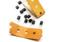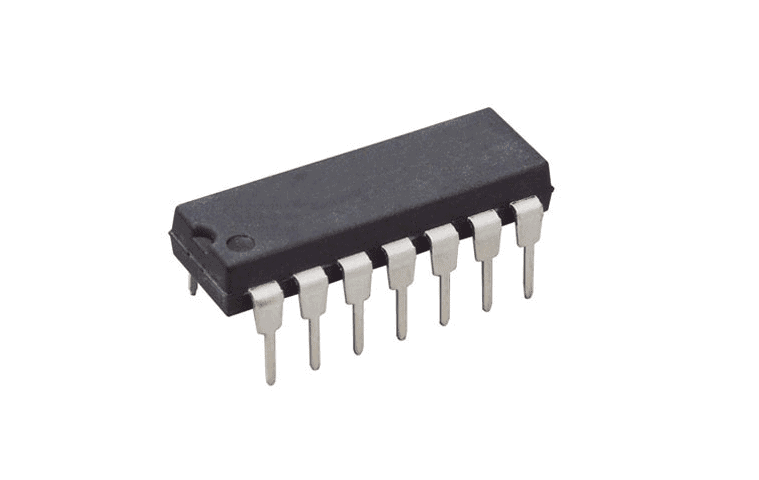
The 74HC14 comes in a DIP form factor and in SMD variants.
Discrete logic circuits are not very common in modern digital systems, but DIP logic components still have their place in many electronics products. Specialty measurements, moderate-power low-frequency analog systems, electromechanical systems, and power products can all use specialty logic for critical functions, especially when the application area is too harsh for an MCU.
Components like the 74HC14 are often used in educational settings or in specialty logic applications, but it is still a useful component as a rugged low-voltage comparator with a wide operating temperature range. There is not one specific 74HC14 datasheet, as this component has become generic over time, however, this article attempts to break down the relevant specifications for various 74HC14 variants.
What’s in the 74HC14 Datasheet?
The 74HC14 hex Schmitt trigger is available in several form factors, but most designers are likely familiar with the basic DIP package used in classes or in more rugged through-hole systems. The 74HC14 was originally designed and introduced by Fairchild Semiconductor, but today’s component manufacturers still manufacture their own versions of the 74HC14 with different packaging. Like many components in the original 74xxxx series of specialty logic from Fairchild, vendor-specific variants have their own datasheets, and designers should not assume all operational specifications are the same across datasheets. With this in mind, there are some points in a 74HC14 datasheet that are common to many variants, particularly those with DIP packages or equivalent SMD packages.
Common Electrical Specifications
All 74HC14 components contain 6 Schmitt trigger inverter circuits with some common electrical specifications. The 74HC logic family is a standard CMOS logic family that has compatible logic levels with NMOS and TTL logic gates. With added pullup resistors, a single Schmitt trigger in a 74HC14 can drive up to 10 LSTTL loads.
| Supply voltage | 2.0 V to 6.0 V (7.0 V maximum) |
| Propagation delay | 11 ns typical, depends on supply voltage |
| Rise/fall time | 12 ns typical, 22 ns guaranteed |
| Input and output voltage ranges | Input: Rail-to-rail (0 to Vcc) +/- 1.5 V
Output: Rail-to-rail (0 to Vcc) +/- 0.5 V |
| Input and output current ranges | Input: +/- 20 mA per pin
Output: +/- 25 mA per pin |
Like other CMOS logic components, the junction capacitance on the internal MOS transistor buffer circuits is voltage-dependent, so the rise and fall times will depend on the supply voltage given to the component. A higher supply voltage gives lower rise/fall times and lower propagation delay. In addition, the rise/fall time specifications quoted above depend on the value of the load capacitance they are driving. The values above (and most 74HC14 datasheets) give a value at 50 pF, but common values for load capacitance can be as low as 1 to 10 pF for modern logic circuits.
Common Pinout
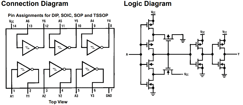
74HC14 components with inlined pin packages (both SMD and through-hole) all have a common pinout. The dimensions for each pinout are not perfectly interchangeable, but they do follow standard hole and land patterns for through-hole and SMD components, respectively.
The common pinout for 74HC14 components and the logic diagram for each inverter are shown below. Here, we have a standard CMOS buffer architecture and pinout that matches the 74LS14 and 74HC04 pin configurations. Note that the 74HC04 is simply a comparator with identical pinout, while the 74HC14 has a 20% to 25% hysteresis window on each pin as described above. One should note that other components in the 74HC logic family are designed to have compatible pinout with the 74LS logic family, and components in each logic family can be easily swapped in a physical layout.
The 74HC14 comes in a DIP form factor and in SMD variants.
Although the pinouts are the same across these components, they do not have identical land patterns and pad dimensions, so be careful when simply swapping one 74HC14 component for another variant. Be sure to check each component datasheet for land pattern/pad size differences to ensure compatibility.
Typical Applications
The 74HC14 was created at a time before every application was targeted with specialty ICs, so the 74HC14 could conceivably be used in a broad range of applications. Principle among these is square wave signal conditioning and cleanup, as the 74HC14 functions as a comparator and the built-in hysteresis provides noise immunity on the input terminals. This makes it a good candidate for accepting low-level signals in industrial applications or other areas where signals may be noisy.
Where to Find a 74HC14 Datasheet and CAD Models
CAD models for 74HC14 components are easy to create, as these parts come in common packages with standardized land/hole patterns. Newer designers may not want to take the time to create these from scratch, and it’s generally not a good idea to simply copy footprints between components. Some manufacturers will release CAD models in specific ECAD software formats, but designers still need a resource where they can find accurate CAD models for their components.
The easiest way to find a 74HC14 datasheet, variants, and other components is to use an electronics search engine such as the one offered by Ultra Librarian. When you use Ultra Librarian, you’ll have access to updated datasheets, technical specifications, CAD data, and verified 3D models that can be imported into popular ECAD applications. You’ll also have access to sourcing information from worldwide distributors.
Working with Ultra Librarian sets up your team for success to ensure streamlined and error-free design, production, and sourcing. Register today for free.