
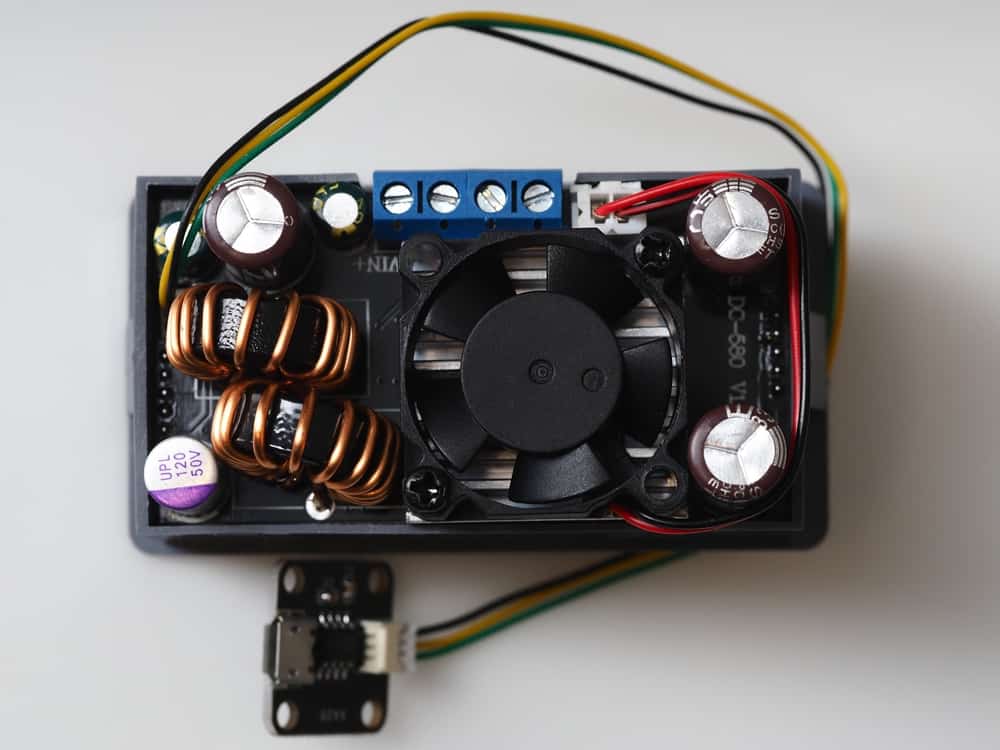
The buck converter is an essential element for many PCB designs
What makes the world go around? That is easy, power makes the world go around. Or more specifically, electrical power that supplies everything from wearables and mobile devices to telecommunications to automotives to aerospace systems.
Regardless of the electrical or electromechanical application, reliable power delivery is critical for operational integrity and performance. For circuit boards and electronics, this requirement typically necessitates determining the best power converter for your design. Often, comparing a synchronous buck converter vs buck converter is the path to making the best selection.
Synchronous Buck Converter vs Buck Converter
Both synchronous buck converters and buck converters are used when a supplied voltage needs to be stepped down for distribution to a load or loads at a lower level. However, there are differences, as listed below.
As evident by the comparison above, choosing between a synchronous buck converter vs a buck converter depends on having a good understanding of the attributes and operation of each.
Buck Converter Operation
As shown below, the basic buck converter circuit is comprised of common passive components. 1
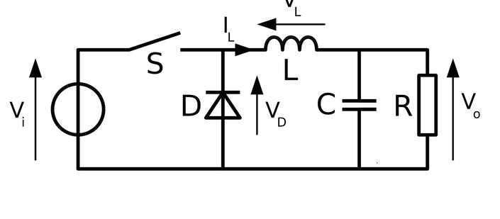
Buck converter circuit diagram. Image source.
The buck converter functions as a step-down voltage regulator. This is accomplished by closing (ON state) and opening (OFF state) the switch, S, at specified intervals.
ON State: When S is closed, current is applied to the inductor, L, which produces a voltage potential that opposes the source voltage, Vi. This action causes the load voltage, Vo, to be less than the source. Over time, the change rate of inductor current will decrease. A corresponding voltage decrease across the inductor will occur and the load voltage will increase. Simultaneously, energy from the inductor is stored in a magnetic field.
OFF State: When the switch is opened while the inductor voltage is not zero, the load voltage is less than the source. During OFF state, the inductor supplies the current to the load from the stored energy in its magnetic field. This condition continues as long as the diode is forward-biased and conducting.
The output voltage is determined by the duty cycle, D, of the buck converter, as shown in Eq. (1), below.
Vo = D x Vi , where 0 ≤ D ≤ 1 (1)
D, which is set by the circuit time constant, is the ratio of ON state time to total period time; therefore, it defines the percentage of the input voltage that is applied to the load.
Synchronous Buck Converter Operation
The basic circuit for the synchronous buck converter is shown below.
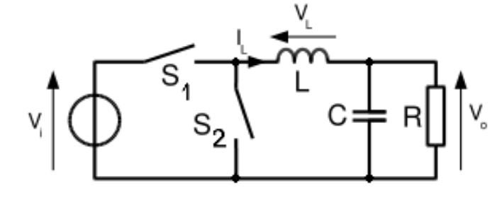
Synchronous buck converter circuit. Image source.
When graphically comparing the synchronous buck converter vs the buck converter, they are quite similar. However, the replacement of the diode with a second switch has significant impact on operation and performance. In contrast to the basic buck converter, where the diode automatically turns on and off based on the voltage across it, both switches are controllable for the synchronous converter. This flexibility allows for greater duty cycle control and it reduces the power loss associated with the diode. The absence of the diode also enables reverse current flow through the converter which can be utilized for regenerative braking or essentially acting as a boost converter–input voltage is increased while current is decreased.
Optimizing PCB Buck Converter Design
Controlling the power delivered to the load is an essential requirement for all electrical and/or electromechanical systems. In some cases, where output voltage must be strictly maintained under varying environmental conditions, a voltage reference may be the best design option. However, when output regulation must be coupled with stepping down a power supply voltage, the buck converter is typically used. For the best results, guidelines as shown below should be followed.
The above guidelines are applicable for basic buck and synchronous buck converter design. Following these and choosing your converter type based on attributes; such as dimension requirements, operation, and cost will aid you in optimizing your power distribution circuit design.
If you’re looking for CAD models for common components or synchronous buck converter vs buck converter, Ultra Librarian helps by compiling all your sourcing and CAD information in one place.
Working with Ultra Librarian sets up your team for success to ensure streamlined and error-free design, production, and sourcing. Register today for free.


")


